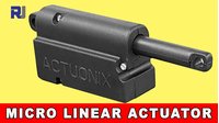
Introduction and Test of Actuonix PQ-12-P Micro Linear Actuator
This guide introduces the Actuonix PQ-12-P Micro Linear Actuator, a compact and versatile component for adding precise linear motion to your robotics and electronics projects. Unlike a standard servo motor that rotates, this actuator pushes or pulls a rod in a straight line, making it ideal for applications requiring controlled movement. This review and test will walk you through its features, specifications, and how to get it moving using both a simple power source and an RC transmitter, providing a clear starting point for your own builds.
Here are a few practical examples of what you can build with this actuator:
- Robotic Hands: Use one actuator per finger to create a realistic and functional robotic gripper.
- Automated Mechanisms: Build a device to push or pull a physical switch, latch, or lock.
- Model & RC Projects: Control flaps, landing gear, or other moving parts on model airplanes or vehicles.
- Camera Motion: Create a precise slider or pan-tilt mechanism for camera movement.
- Educational Demonstrations: Teach the principles of linear motion, gear reduction, and servo control.
Hardware Components
To follow along with this project, you will need the following components:
- Actuonix PQ-12-P Micro Linear Actuator (6V model used in this guide)
- 5V or 6V DC power supply
- RC Transmitter and Receiver (e.g., FlySky FS-i6 and FS-iA6) for wireless control
- Jumper wires
Understanding the Actuonix PQ-12-P
The PQ-12-P is a small, all-plastic linear actuator. In the video, the presenter highlights its key specifications, which are crucial for determining if it fits your project's needs. The model tested is the PQ12-63-6-P, which indicates a 63:1 gear ratio and a 6-volt operating voltage (in video at 01:05).
Here are the key technical details from the datasheet discussed in the video (in video at 02:04):
- Peak Power Point: 30 Newtons at 8 mm/second
- Peak Efficiency Force: 45 Newtons
- Maximum Side Load: 10 Newtons
- Stroke Length: 20 millimeters
- Stall Current (at 6V): 210 milliamps. This is an important figure to note, as your power supply must be able to handle this current draw.
The model number breakdown is simple: "PQ12" is the product family, the "63" refers to the gear ratio, the "6" is the voltage, and the "P" indicates it includes a position feedback sensor. The video also mentions that the actuator's weight is 22.5 grams and its extended length is 66.6 millimeters, making it a very compact component.
Wiring Guide
Wiring the PQ-12-P is straightforward, as it uses a standard 3-pin servo-style connector. This makes it compatible with many existing systems.
The wiring is identical to a standard servo motor (in video at 05:22):
- Ground (Brown/Black): Connect to the negative terminal of your power supply.
- Power (Red): Connect to the positive terminal of your power supply. The video demonstrates operation at 5V, but notes that 6V is the rated voltage for optimal performance.
- Signal (White/Yellow): This wire receives the Pulse Width Modulation (PWM) signal that controls the actuator's position.
This simple wiring scheme allows for easy integration with Arduino boards, RC receivers, or servo controllers.
Testing and Demonstration
The video provides two excellent methods for testing your actuator.
Method 1: Using a Servo Tester
The simplest way to test the actuator is with a standalone servo tester. This device provides the necessary power and generates the PWM signal without needing a separate controller. By connecting your 5V power supply to the tester's input and the actuator to its output, you can use the tester's knobs and switches to manually extend and retract the actuator (in video at 06:51).
Method 2: Using an RC Transmitter and Receiver
For a more dynamic test, the presenter uses a FlySky FS-i6 transmitter and FS-iA6 receiver (in video at 07:55). The actuator is connected to one of the receiver's output channels. This setup allows for wireless control of the actuator.
The demonstration shows how the actuator responds to different types of inputs:
- Joystick Channels (1-4): The actuator's position is proportional to the joystick's position. Moving the stick forward extends the actuator, while pulling it back retracts it. The response is smooth and precise, though there is a slight delay due to the high gear ratio (in video at 09:38).
- Switch Channels (5-6): These channels are controlled by switches on the transmitter. A two-position switch will fully extend or retract the actuator, while a three-position switch offers a middle position as well (in video at 11:02).
This test demonstrates the actuator's versatility and its ability to be controlled by standard RC equipment, making it a great choice for remote-controlled projects.
Chapters
- [00:00] Introduction and Product Overview
- [00:21] Applications and Package Contents
- [01:26] Manufacturer Details and Pricing
- [02:04] Datasheet and Technical Specifications
- [04:25] Wiring and Pinout Explanation
- [06:51] Testing with a Servo Tester
- [07:55] Wireless Control with an RC Transmitter
- [11:42] Conclusion and Final Thoughts
Ressources et références
Aucune ressource pour le moment.
Fichiers📁
Aucun fichier disponible.