16 Channel Relay module 5V relay voltage fixed
Introduction
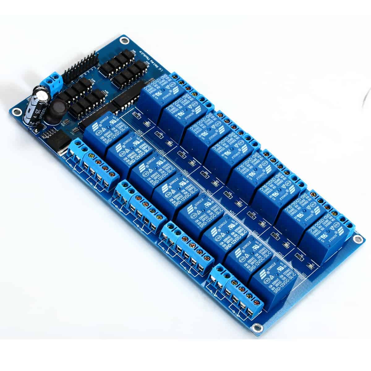
This project addresses a critical design flaw found in many 16-channel 5V relay modules. While these modules are marketed as 5V devices, the voltage regulator on board often only supplies the regulated 5V to the optocoupler circuitry, leaving the actual relay coils to receive the full, unregulated input voltage. If you power the module with anything higher than 5V—such as a 9V or 12V supply—you risk damaging the relays and any connected devices.

This guide demonstrates a simple and effective hardware fix to ensure the relay coils always receive the correct 5V, regardless of the input voltage. This is a crucial modification for any project where reliability is key. Here are a few practical applications where this fix is essential:
- Building a home automation hub that controls 16 different appliances (lights, fans, heaters) from a single, higher-voltage power supply.
- Creating an industrial control panel where a 24V industrial supply is used, but the logic and relays require a stable 5V.
- Upgrading an existing 16-channel relay board to handle a wider range of input voltages without the risk of component failure.
Hardware Overview
The core of the problem lies in the module's power distribution. The input voltage (e.g., 12V) is fed to a voltage regulator (often an LM2596) which steps it down to a clean 5V. However, this regulated 5V is only routed to power the optocouplers, which isolate the control signals. The relay coils and the ULN2003 driver chips are mistakenly connected directly to the raw input voltage line. This means a 12V input would supply 12V to the 5V relay coils, causing them to overheat and eventually fail.
The video demonstrates this issue clearly. With an input of 8.72V, the relay coil is measured receiving 7.75V, which is dangerously high for a 5V-rated component (in video at 03:17).
Hardware/Components
- 16-Channel 5V Relay Module
- Soldering iron and solder
- Wire cutter/stripper
- A sharp knife or cutting tool
- A piece of hook-up wire
- Multimeter for testing
- Power supply (e.g., 9V or 12V) for testing
Wiring Guide
The fix involves a simple rewiring procedure. The goal is to disconnect the power trace that feeds the ULN2003 chips and the relay coils from the raw input and instead connect them to the regulated 5V output. The video provides a detailed schematic of the corrected circuit (in video at 03:45).
Here is the step-by-step process demonstrated in the video:
- Identify the Power Trace: First, trace the PCB tracks to find where the raw input voltage is routed to the ULN2003 driver chips. In the video, this is a track that runs underneath a capacitor to the pin 1 of the driver chips (in video at 05:15).
- Cut the Trace: Using a sharp knife, carefully cut this power trace. This disconnects the driver chips and relay coils from the raw input voltage. The video shows this cut being made at 05:56.
- Verify the Disconnection: Use a multimeter in continuity mode to confirm that the input voltage is no longer reaching the driver chips (in video at 06:11).
- Solder a New Wire: Solder a new wire from the regulated 5V output point (which was previously only feeding the optocouplers) to the now-disconnected power point that feeds the driver chips and relays. The video shows passing the wire through an existing hole on the board to reach the common pin of the relays (in video at 07:06).
- Test the Fix: Power the module with a voltage higher than 5V (e.g., 15V) and verify with a multimeter that the relay coils now receive exactly 5V (in video at 07:37).
Code Explanation
The provided Arduino code is a simple test program to cycle through all 16 relay channels. You can use it to verify your hardware fix works correctly.
The most important part for you to configure is the controlPin array. This defines which Arduino pins are connected to the relay module's input pins.
const int controlPin[16] = {2,3,4,5,6,7,8,9,10,11,12,A0,A1,A2,A3,A4}; // define pins
Modify this list to match your actual wiring. The code uses digital pins 2-12 and analog pins A0-A4, but you can change these to any available digital I/O pins on your board.
Another key variable is triggerType. This is set to LOW by default, which is common for many relay modules.
const int triggerType = LOW;// your relay type
If your relay module is "active HIGH" (meaning you send a HIGH signal to turn it ON), you can change this to HIGH. The channelControl() function handles the logic for both types, so you only need to adjust this one variable.
Finally, the loopDelay variable controls the pause between each channel in the test cycle.
int loopDelay = 1000;// delay in loop
You can adjust this to make the test faster or slower.
Live Project/Demonstration
After the fix, the video demonstrates the module working perfectly with a 15V input. The multimeter shows the input voltage at 15V, while the regulated voltage at the relay coil is a stable and safe 5V (in video at 08:10). The relays click on and off as expected, confirming the fix is successful and the module can now handle higher input voltages without damage.
Chapters
- [00:00] Introduction to the 16-Channel Relay Voltage Problem
- [00:34] Identifying the Design Flaw
- [01:56] Demonstrating the Voltage Issue
- [03:45] Schematic of the Corrected Circuit
- [05:07] Cutting the Incorrect Power Trace
- [06:34] Soldering the New 5V Connection
- [07:37] Testing the Fix with 15V Input
- [08:24] Conclusion and Final Thoughts
Images


/*
 * Arduino code to control 16 channel relay with Arduino UNO
 *
 * Written by Ahmad Shamshiri for Robojax.com on Sunday, October 8, 2018
 * at 10:35 in Ajax, Ontario, Canada
 * Watch video instructions for this code: https://youtu.be/Q9aBI4ELKC4
 *
 * This code is "AS IS" without warranty or liability. Free to be used as long as you keep this note intact.
 * This code has been downloaded from Robojax.com
    This program is free software: you can redistribute it and/or modify
    it under the terms of the GNU General Public License as published by
    the Free Software Foundation, either version 3 of the License, or
    (at your option) any later version.

    This program is distributed in the hope that it will be useful,
    but WITHOUT ANY WARRANTY; without even the implied warranty of
    MERCHANTABILITY or FITNESS FOR A PARTICULAR PURPOSE.  See the
    GNU General Public License for more details.

    You should have received a copy of the GNU General Public License
    along with this program.  If not, see <https://www.gnu.org/licenses/>.
 */


const int controlPin[16] = {2,3,4,5,6,7,8,9,10,11,12,A0,A1,A2,A3,A4}; // define pins

const int triggerType = LOW;// your relay type
int loopDelay = 1000;// delay in loop
int tmpStat =1;


void setup() {
  for(int i=0; i<16; i++)
  {
    pinMode(controlPin[i], OUTPUT);// set pin as output
    if(triggerType ==LOW){
      digitalWrite(controlPin[i], HIGH); // set initial state OFF for low trigger relay
    }else{
       digitalWrite(controlPin[i], LOW); // set initial state OFF for high trigger relay
    }
  }

  Serial.begin(9600);// initialize serial monitor with 9600 baud
}

void loop() {

  for(int i=0; i<16; i++)
  {

   channelControl(i,tmpStat,200);// turn each relay ON for 200ms


  }
  if(tmpStat)
  {
    tmpStat=0;
  }else{
    tmpStat=1;
  }
 Serial.println("===============");
 //channelControl(6,1, 2000); // turn relay 7 ON for 2 seconds
 //channelControl(6,0, 5000); // turn relay 7 OFF for 5 seconds
 //channelControl(9,1, 3000); // turn relay 10 OFF for ever

 delay(loopDelay);// wait for loopDelay ms

}

/*
 * funciton: channelControl
 * turns ON or OFF specific relay channel
 * @param relayChannel is integer value channel from 0 to 15
 * @param action is 1 for ON or 0 for OFF
 * @param t is time in milliseconds
 */
void channelControl(int relayChannel, int action, int t)
{
  int state =LOW;
  String statTXT =" ON";
  if(triggerType == LOW)
  {
    if (action ==0)// if OFF requested
    {
      state = HIGH;
      statTXT = " OFF";
    }
    digitalWrite(controlPin[relayChannel], state);
    if(t >0 )
    {
      delay(t);
    }
       Serial.print ("Channel: ");
       Serial.print(relayChannel);
       Serial.print(statTXT);
       Serial.print(" - ");
       Serial.println(t);
  }else{
    if (action ==1)// if ON requested
    {
      state = HIGH;
    }else{
      statTXT = " OFF";
    }
    digitalWrite(controlPin[relayChannel], state);
    if(t >0 )
    {
      delay(t);
    }
       Serial.print ("Channel: ");
       Serial.print(relayChannel);
       Serial.print(statTXT);
       Serial.print(" - ");
       Serial.println(t);
  }

}
Nko o na nki.
-
Amazon16 Channel 5V relay moduleamzn.to
-
eBay
-
eBay
-
AliExpressPurchase 16 Channel 5V, 12V or 24V relay module from AliExpresss.click.aliexpress.com
-
BanggoodPurchase 16 Channel relay module from Banggoodbanggood.com
Mokili na bisika
-
L'extérieur16 Channel Relay module 5V relay voltage fixedyoutube.com
-
L'extérieurDIP 4-pin photocouplerwebpagefx.com
-
L'extérieur
-
L'extérieurPurchase 16 Channel 5V, 12V or 24V relay module from AliExpresss.click.aliexpress.com
-
L'extérieurPurchase 16 Channel relay module from Banggoodbanggood.com
-
L'extérieur
Fichiers📁
Schematic
-
robojax_16ch_relay module schematic
robojax_16ch_relay_schematic.pdf0.37 MB