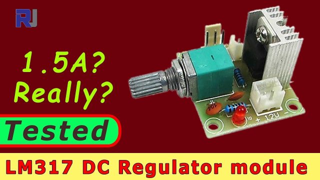
Test review of LM317 DC Voltage regulator module
In this tutorial, we will explore the LM317 voltage regulator module, examining its capabilities and limitations. This device is commonly used to provide a stable output voltage from a variable input voltage, making it useful for various electronic applications. We will test its input and output voltage ranges, as well as its current handling capacity.

During our exploration, we will detail the wiring, specifications, and expected behaviors of the LM317 module. For a clearer understanding, make sure to check out the video at the specified timestamps for visual guidance.
Hardware Explained
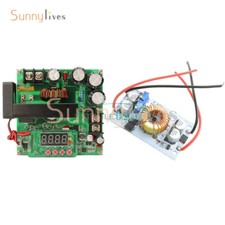
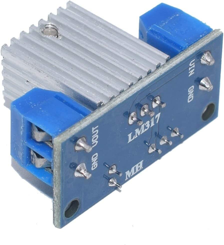
The LM317 is a versatile voltage regulator that can output voltages between 1.25V and 37V, with a maximum output current of 1.5A. It features three terminals: input, output, and adjust. The adjust pin works in conjunction with two resistors and a potentiometer to set the desired output voltage. This module also includes a heatsink to manage thermal dissipation, which is crucial during operation at higher currents.
When using this module, it's essential to note that the input voltage should not exceed 40V, and the output is limited to a maximum of approximately 13.5V due to design constraints. The onboard potentiometer allows for fine-tuning the output voltage, making the LM317 adaptable for various applications.
Datasheet Details
| Manufacturer | Texas Instruments |
|---|---|
| Part number | LM317T |
| Logic/IO voltage | 1.25–37 V |
| Supply voltage | 40 V max |
| Output current (per channel) | 1.5 A max |
| Peak current (per channel) | 1.5 A |
| PWM frequency guidance | N/A |
| Input logic thresholds | N/A |
| Voltage drop / RDS(on) / saturation | 3 V max (typ.) |
| Thermal limits | 150 °C junction temperature |
| Package | TO-220 |
| Notes / variants | Various packages available |
- Input voltage should be limited to 40V max.
- Output voltage is adjustable between 1.25V and 13.5V.
- Ensure adequate heatsinking for higher currents.
- Watch for thermal overload protection kicking in at high temperatures.
- Use a potentiometer for fine-tuning output voltage.
- Verify input-output voltage difference to avoid overheating.
- Be cautious with the polarity of connections.
- Monitor output current to stay within safe limits.
Wiring Instructions
Wiring the LM317 module is straightforward. Begin by connecting the input voltage to the designated input terminal on the module. Ensure that this input voltage does not exceed 40V. Next, connect the output terminal to your load, which could be a fan, sensor, or any other component that requires regulated voltage.
For the adjust pin, connect it to the potentiometer and ensure that the other end of the potentiometer is connected to ground. This setup allows you to adjust the output voltage by turning the potentiometer. Make sure to double-check the polarity of the connections; the module uses a non-standard color coding where the black wire indicates positive and the red wire indicates negative, so take care to avoid any accidental damage.
Demonstration / What to Expect
When testing the LM317 module, you can expect it to provide stable output voltage when the input is within the specified range. It's crucial to monitor the output current, as exceeding 0.5A can lead to significant heating and potential thermal shutdown (in video at 12:30). Users should avoid pushing the module to its limits, especially at lower output voltages with high input voltages, as this can increase power dissipation and heat generation.
Video Timestamps
- 00:00 Hardware explained
- 04:21 Voltage Regulation is tested
- 07:41 output Load test
تصاویر
مواردی که ممکن است به آنها نیاز داشته باشید
-
آمازونPurchase 5pcs/10pcs LM317 regular module from AliExpresss.click.aliexpress.com
-
آمازون
-
علیاکسپرسPurchase LM317 regular module from AliExpresss.click.aliexpress.com
منابع و مراجع
هنوز هیچ منبعی موجود نیست.
فایلها📁
برگه مشخصات (pdf)
-
LM317 regulator datasheet
lm317_regulator_datasheet.pdf2.34 MB