Programmable Resistor 9.999999M? Explained with Schematic
Introduction
This guide explores a fascinating piece of test equipment: the programmable resistor module. This device allows you to dial in a precise resistance value from 0 to 10MΩ using a series of rotary switches and jumper caps, offering a level of flexibility that is incredibly useful for electronics work. Instead of hunting through bins for a specific resistor value, you can set it instantly on this module. Its real-world value lies in its ability to simulate sensors, create precise voltage dividers, test circuits under different load conditions, and calibrate other instruments.
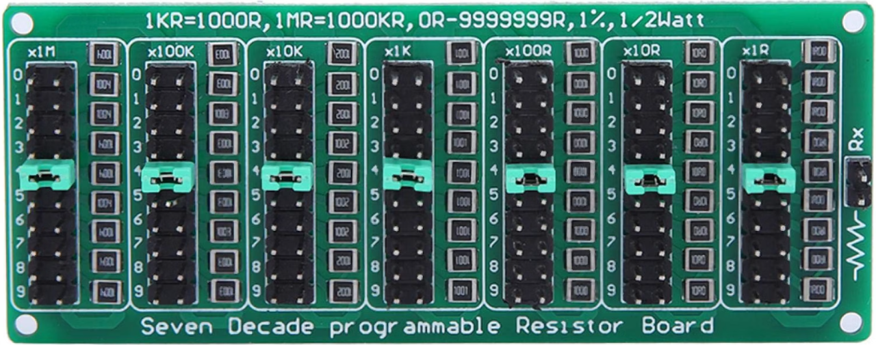
Here are some practical ways you can use this programmable resistor in your own projects:
- Simulating Sensors: Replace a thermistor or light-dependent resistor (LDR) with a fixed value to test your circuit's response in a controlled environment.
- Calibrating Instruments: Provide a known, precise resistance to calibrate an ohmmeter, a Wheatstone bridge, or other measurement devices.
- Testing Power Supplies: Use it as a constant load to test the voltage regulation of a power supply under different load conditions.
- Setting Timing Constants: In an RC (resistor-capacitor) timing circuit, you can use the programmable resistor to fine-tune the time delay without swapping components.
- Creating Voltage Dividers: Build a precise voltage divider to generate a specific reference voltage for an analog-to-digital converter (ADC).
Hardware Overview
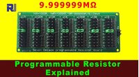
The module is a compact board with a series of rotary switches and jumper positions. Each switch controls a decade of resistance (ones, tens, hundreds, thousands, etc.). The jumper caps are used to select the specific resistor value within that decade. The module is designed for 1% tolerance resistors, ensuring high accuracy.
Here is a breakdown of the key components:
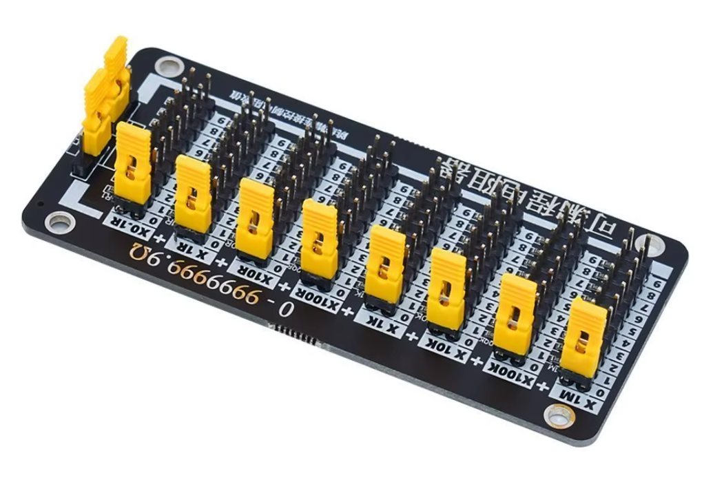
- Rotary Switches: Each switch corresponds to a multiplier (1, 10, 100, 1k, 10k, 100k, 1M). You set the digit for each decade by turning the switch.
- Jumper Positions: For each rotary switch, there are positions (0-9). You place a jumper cap on the desired number to select the resistance value for that decade.
- Output Terminals: These are the two points where you connect your multimeter or circuit to measure the resulting resistance.
Wiring Guide
This module is not a typical component that requires wiring to a microcontroller. It is a passive device used in a circuit. To use it, you simply connect your circuit or measurement tool to the two output terminals on the module. The module itself does not require any power supply.
To set a resistance value, you must configure the rotary switches and jumper caps. For example, to set a resistance of 416Ω, you would set the switch for the hundreds place to "4" and place the jumper on the "4" position. You would then set the tens place to "1" and place its jumper on "1", and finally set the ones place to "6" and place its jumper on "6". All other switches and jumpers should be set to "0".
If the transcript mentions a wiring diagram, it would be inserted here.
Live Demonstration and Testing
The video transcript includes a live demonstration where the presenter tests the module's accuracy with a multimeter. The module is first set to 416Ω, and the multimeter reads approximately 415Ω, which is within the expected tolerance. The presenter then demonstrates that removing a jumper cap results in an open circuit, showing how the jumpers create the electrical path.
Further tests show the module accurately producing values like 7,216Ω, 84.673kΩ, and up to 9.993MΩ, confirming its precision across its entire range. The demonstration highlights the module's utility for achieving exact resistance values that are not available with standard resistors.
Conclusion
This programmable resistor module is an excellent tool for any electronics enthusiast or professional. Its ability to provide precise, adjustable resistance values from 0 to 10MΩ makes it invaluable for testing, prototyping, and calibration. The 1% tolerance resistors ensure that the values you set are accurate, and the simple interface makes it easy to use.
Chapters
- [00:06] Introduction to the Programmable Resistor Module
- [00:21] Understanding the Module's Layout and Switches
- [00:56] How the Resistors are Connected in Series
- [01:25] Detailed Look at the Internal Circuitry
- [03:57] Physical Dimensions and Weight of the Module
- [04:39] Schematic and Example Configurations
- [05:31] Setting the Module to Zero Ohms
- [06:08] Setting a Specific Resistance Value (5Ω)
- [06:27] Example: Configuring a 4.2MΩ Resistance
- [07:10] Live Testing and Accuracy Verification
- [08:16] Demonstrating an Open Circuit Condition
- [09:05] Testing Higher Resistance Values (kΩ and MΩ)
Images
Things you might need
-
AmazonBuy Programmable Resistor 9.999999MΩ from Amazonlink.amazon
-
eBay
-
AliExpressBuy Programmable Resistor 9.999999MΩ from AliExpresss.click.aliexpress.com
Resources & references
No resources yet.
Files📁
No files available.