Review of Benewak TFMini Plus LiDar laser 12m distance sensor
In this tutorial, we will explore the Benewak TFMini Plus LiDar laser distance sensor, which boasts an impressive range of up to 12 meters. This sensor is particularly noteworthy for its affordability and performance, making it an attractive option for various projects. We will review its hardware, wiring, and basic usage to help you understand how to integrate it into your own applications. If you want to see detailed demonstrations, be sure to check the video linked (in video at 00:00).

Hardware Explained
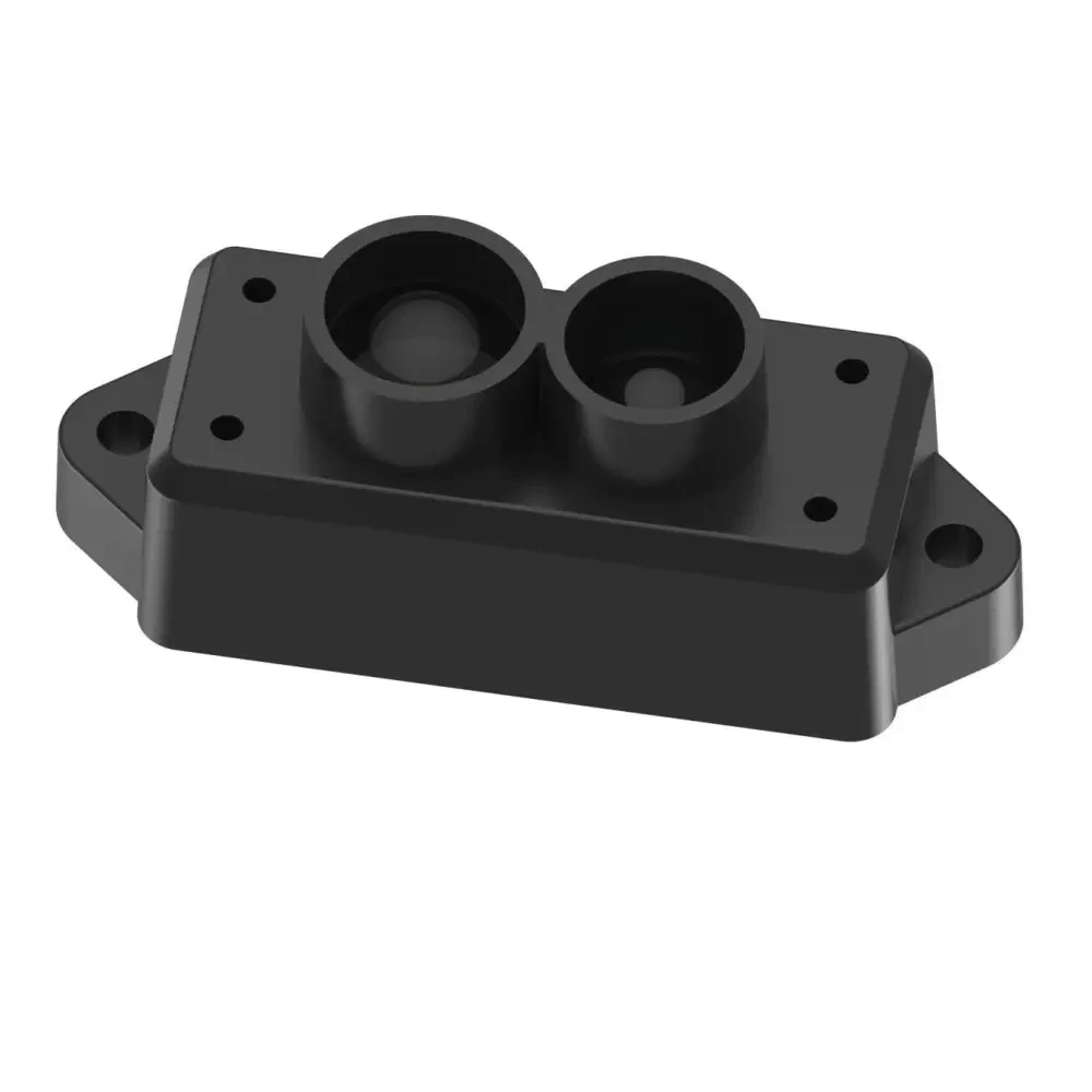
The TFMini Plus is a compact LiDar sensor that measures distances using a laser. It operates within a range of 0.1 to 12 meters and communicates over UART or I2C, providing flexibility for integration with microcontrollers like Arduino or Raspberry Pi. This sensor is designed for both indoor and outdoor use, featuring a waterproof and dustproof housing.
One of the key features of the TFMini Plus is its accuracy, which can reach ±1 cm at distances greater than 5 meters. It has a frame rate of up to 1000 Hz, allowing for rapid distance measurements. This enables applications such as obstacle detection and distance measuring in robotics and automation.
Datasheet Details
| Manufacturer | Benewak |
|---|---|
| Part number | TFMini Plus |
| Operating range | 0.1 to 12 m |
| Frame rate | 1 to 1000 Hz |
| Operating temperature | -20 to 60 °C |
| Accuracy | ±1 cm (5 m to 12 m) |
| Power supply voltage | 5 V |
| Average current | < 110 mA |
| Central wavelength | 850 nm |
| Weight | 13.5 g |
- The sensor has a minimum detection radius of 36 cm at 12 m.
- It can operate in both UART and I2C communication modes.
- Ensure proper power supply to avoid damage.
- Accuracy is affected by surface reflectivity; ideally, use targets with high reflectivity.
- Utilize the provided software for easy data logging and analysis.
Wiring Instructions
To wire the TFMini Plus sensor, start by connecting the power supply. The red wire from the sensor should connect to the 5 V pin on your microcontroller, while the black wire should go to the ground (GND). For the data communication, the white wire labeled as TX on the sensor connects to the RX pin on your microcontroller, and the RX wire from the sensor connects to the TX pin on your microcontroller. This setup allows the sensor to send distance measurements back to your microcontroller.
Ensure that the connections are secure and double-check the pin assignments to avoid any miscommunication. If you are using a USB to UART converter, the connections will remain the same, but ensure that the converter is powered properly. This wiring method is straightforward and should allow you to get started with your sensor quickly.
Demonstration / What to Expect
When you power up the TFMini Plus and establish communication, you can expect to see rapid distance measurements on your serial monitor. If you hold the sensor steady, the readings should stabilize, showing accurate distances to nearby objects. Be cautious of potential pitfalls, such as incorrect wiring or insufficient power supply, which could lead to erratic readings (in video at 03:00).
As demonstrated in the video, the sensor can effectively measure distances even through glass, which is a common question among users. Be sure to test the sensor at various distances and surfaces to fully understand its capabilities and limitations.
Video Timestamps
- 00:00 Start
- 00:38 Introduction
- 06:21 Wiring Explained
- 08:44 Demonstration
- 14:16 Issue with the software
Images
Resources & references
No resources yet.
Files📁
No files available.