How to test Servo motor with 3 channel Cheap Servo Tester
Servo motors are the workhorses behind countless robotics, RC, and automation projects, but before integrating them into a complex build, it's crucial to know they function correctly. This guide demonstrates a simple, effective method for testing up to three SG90 servo motors simultaneously using a dedicated, low-cost servo tester. This tool is essential for any maker, allowing you to quickly verify motor operation, find the neutral position, and run a continuous sweep test without needing a microcontroller or complex wiring. This practical approach is perfect for:
- Bench Testing: Verifying that new or salvaged servos are functional before installing them in a project.
- RC Hobbyists: Checking the operation of steering and throttle servos in cars, boats, and planes outside of the vehicle.
- Robotics Builders: Calibrating the range of motion for robotic arms or pan-tilt camera systems.
- Educational Projects: Demonstrating the fundamentals of PWM (Pulse Width Modulation) control in a classroom or workshop.
- Troubleshooting: Isolating whether a non-responsive mechanism is due to a faulty servo or a problem with the main controller.
Hardware Components
To follow along with this guide, you will need the following components:
- SG90 or similar micro servo motors (up to 3 for simultaneous testing)
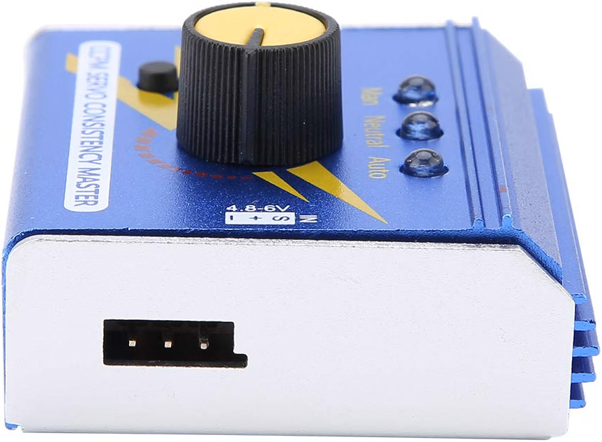
- A 3-channel servo tester (available in metal or plastic housing)
- A 5V power source, such as a battery pack or USB power supply (in video at 02:02)
- Jumper wires (if your power source doesn't have a servo-style connector)
Wiring Guide
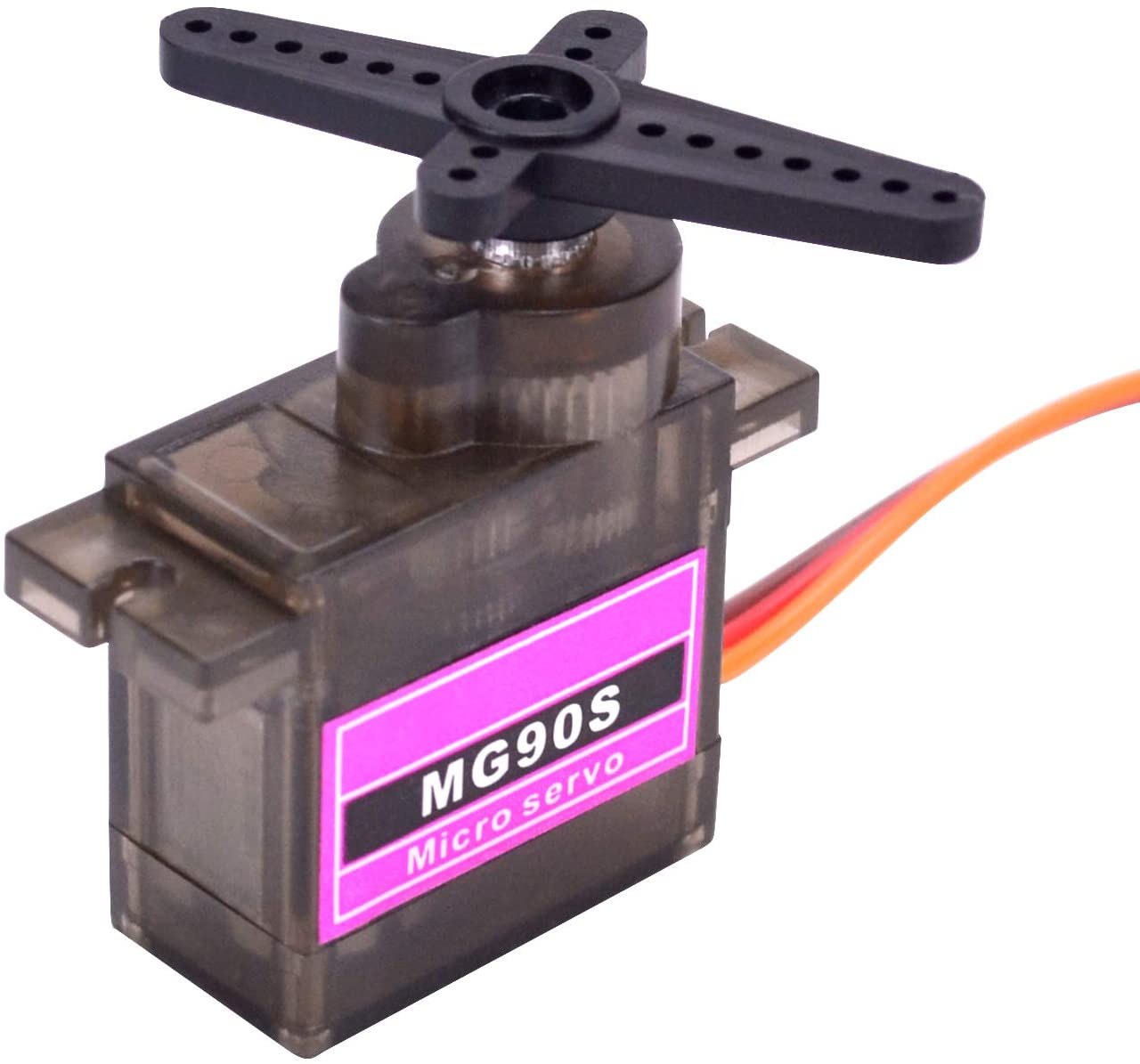
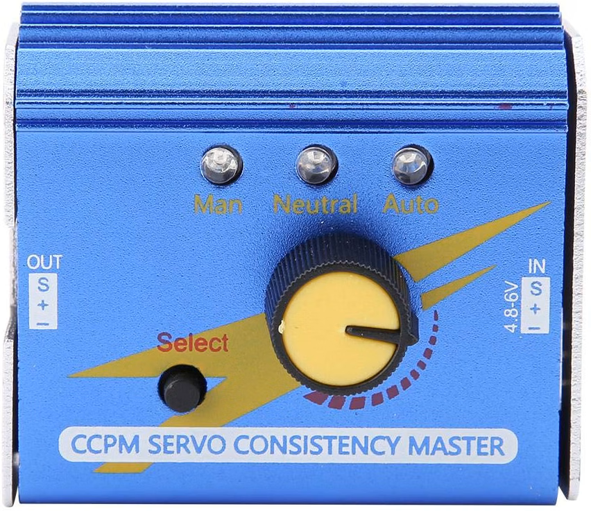
The servo tester simplifies the connection process significantly. The input side of the tester has three pins labeled Negative (-), Positive (+), and Signal (S). You will connect your 5V power source to these pins, ensuring the polarity is correct (in video at 01:48).
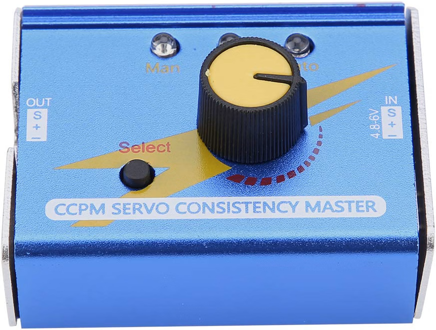
On the output side, there are three identical ports for connecting your servos. Each port also has pins for Negative, Positive, and Signal. The key to a successful connection is observing the wire colors on your servo (in video at 00:54):
- Ground (GND): This is the brown or black wire. It must be connected to the pin labeled Negative (-).
- Power (VCC): This is the red or middle wire. It connects to the Positive (+) pin.
- Signal: This is the orange or yellow wire. It connects to the Signal (S) pin.
Simply insert the servo connectors into the output ports, ensuring the dark (ground) wire is on the same side as the negative pin, as shown in the video. This same wiring logic applies to the metal version of the tester, which has the same connector layout (in video at 04:43).
How the Servo Tester Works
Understanding the tester's modes is key to getting the most out of it. The device features a knob and a "Select" button that cycles through three distinct modes (in video at 03:11):
- Manual Mode: In this mode, the knob directly controls the servo's position. Turning the knob clockwise moves the servo arm from its minimum to its maximum angle. This is perfect for testing the full range of motion and finding specific positions.
- Neutral Mode: Pressing the "Select" button once switches to Neutral mode. This instantly moves all connected servos to their center (90-degree) position. This is especially useful for verifying the center point for applications like RC car steering.
- Auto Mode: Pressing the "Select" button again activates Auto mode. The tester then sends a continuous, sweeping signal that automatically moves the servos back and forth between their minimum and maximum positions. This is an excellent way to stress-test a servo's operation over time.
Live Project Demonstration
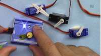
In the video demonstration, three SG90 servos are connected to the tester. The presenter first uses Manual mode to show how the knob moves all servos in unison. He notes that the tester may not drive the servos to the full 180 degrees, but it's more than sufficient for a quick functionality check (in video at 03:22).
Next, he demonstrates the Neutral mode, which brings all servos to their center position. Finally, he switches to Auto mode, where the servos continuously sweep back and forth, confirming they are all operational. The video also shows that the same tester can be used with larger servos like the MG996R, as long as they are tested without a load, as the tester may not provide enough current for heavy-duty operation (in video at 06:20).
Chapters
- [00:00] Introduction and Project Overview
- [00:27] Understanding Servo Motor Basics
- [01:36] Introducing the 3-Channel Servo Tester
- [02:13] Connecting Power and Servos
- [03:11] Testing Servos in Manual Mode
- [03:52] Using Neutral and Auto Test Modes
- [04:43] Testing with the Non-Metallic Version
- [06:08] Testing Larger Servo Motors
- [07:36] Conclusion and Final Thoughts
Images


Things you might need
-
AmazonBasic Servo tester on Amazonamzn.to
-
Amazon
-
Amazon
-
AmazonServo motor on Amazonamzn.to
-
AmazonServo tester on Amazonamzn.to
-
eBay
-
AliExpressServo tester on AliExpresss.click.aliexpress.com
Resources & references
No resources yet.
Files📁
No files available.