DC 10-55V 60A 100A Motor Speed Controller PWM Reverse Control Switch with LED Display Relay
In this project guide, we dive into a comprehensive review and teardown of a high-power DC motor speed controller. This module, capable of handling 10 to 55 volts and claiming a continuous 60-ampere output, is designed to give you precise speed control and direction management for large DC motors. Beyond just a product review, this guide explores the internal components, tests the controller under extreme load, and provides crucial insights into its real-world performance and limitations.
This type of controller is a versatile building block for many ambitious projects. Here are a few practical applications where this module shines:
- Electric Vehicle (EV) Conversions: Controlling the drive motor on a DIY electric go-kart, scooter, or small electric bicycle.
- Industrial Automation: Driving conveyor belts, winches, or other heavy-duty actuators that require variable speed and forward/reverse operation.
- Robotics: Powering the drive motors of large, heavy-duty robots where precise speed and direction control are essential.
- Machine Tools: Retrofitting a drill press, lathe, or milling machine with variable speed control for different materials and cutting operations.
- Pumps and Fans: Controlling high-flow water pumps or industrial ventilation fans where adjusting the flow rate is necessary.
This guide will walk you through the module's features, an internal component analysis, and a detailed thermal performance test to show you what it can really handle.
Hardware Overview
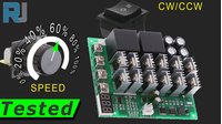
The controller is a compact yet powerful unit, measuring 120mm in length, 99.5mm in width, and 22mm in depth. Its design centers around two large relays for direction control, a bank of MOSFETs for speed modulation, and a control circuit for the user interface. The front panel features a three-way switch for forward, stop, and reverse, a potentiometer for speed adjustment, and an LED display that shows the current PWM duty cycle.
Internally, the module contains several key components that were identified during the teardown (in video at 04:03):
- 555 Timer IC: This chip generates the 15 kHz PWM signal that controls motor speed.
- 7805 Voltage Regulator: A 5V regulator that powers the control logic and display driver.
- XL7015 Buck Converter: A high-voltage buck converter that steps down the input voltage (up to 60V) to a stable 5V for the rest of the circuit.
Wiring Guide
Wiring the module is straightforward, as it uses simple screw terminals. The four terminals on the side are clearly labeled for power input and motor output.
Connect your DC power supply (10-55V) to the terminals labeled + and -. Then, connect your DC motor to the other two terminals. The direction of the motor's rotation can be changed using the three-way switch on the front panel. The module also features a separate on/off switch that controls the signal to the controller, allowing you to stop the motor without cutting the main power.
If a wiring diagram is provided in the video, it will be placed here.
Code Explanation
No code is provided for this project, as it focuses on the hardware review of a standalone motor controller. The module is fully self-contained and does not require programming to operate. However, the reviewer mentions a potential "hack" in the video (in video at 02:02) to allow control via an Arduino. This would involve bypassing the onboard potentiometer to feed an external PWM signal to the 555 timer circuit, but the specifics are not covered in this transcript.
Live Performance Test and Thermal Analysis
The core of this review is the live performance test. The reviewer connected the module to a power supply and an electronic load to simulate real-world conditions and measure its true capabilities.
Basic Functionality: The initial test with a small motor confirmed that the speed control and direction switching work as expected. The controller features a soft-start function, which gradually ramps up the motor speed instead of jumping to the set value, reducing mechanical stress.
Minimum Voltage: The test showed that while the module can operate at lower voltages, it requires the specified 10V input for proper and reliable operation (in video at 09:25).
High-Current Test: The most critical test involved pushing the controller to its limits. The reviewer set the electronic load to 60 amperes, matching the module's continuous current rating. Under this load, the MOSFETs began to heat up rapidly, reaching temperatures over 100°C (in video at 13:44). The temperature continued to climb, eventually exceeding 125°C, forcing the reviewer to shut down the test to prevent damage.
Thermal Imaging: A thermal camera was used to identify the hottest components. The analysis showed that the MOSFETs were the primary source of heat, while the relays remained relatively cool. This indicates that the current rating is primarily limited by the MOSFETs' heat dissipation capabilities.
Reduced Current Test: The test was repeated at lower currents to find a sustainable operating point. At 50 amperes, the temperature still increased. At 40 amperes, the temperature stabilized at around 91-99°C after a few minutes. This suggests that for continuous operation, the module is realistically rated for about 30-40 amperes, not the advertised 60 amperes.
Live Project Demonstration
The demonstration clearly showed the module's strengths and weaknesses. The speed control and direction switching are very responsive and work well. However, the thermal test revealed a critical limitation: the controller cannot sustain its advertised 60-amp continuous current without overheating. For reliable, continuous operation, you should plan for a maximum of 30-40 amperes, or you will need to add an external cooling fan or a larger heatsink to the MOSFETs.
Conclusion
This DC motor speed controller is a good product for its price point, offering robust control features and a solid build quality. However, the advertised 60A rating is misleading. The thermal testing proves that it is best suited for applications drawing 40A or less for continuous use. If your project demands higher currents, you will need to implement additional cooling solutions or consider a more robust controller. For a wide range of medium-power motor control applications, this module provides excellent value and functionality.
Chapters
- [00:00] Introduction and Product Overview
- [01:14] Specifications and Purchase Link
- [02:14] Module Hardware Tour and Component Identification
- [04:03] Internal Component Teardown and Analysis
- [06:39] Basic Speed and Direction Control Test
- [09:25] Minimum Voltage Test
- [10:18] High-Current (60A) Load Test and Thermal Imaging
- [16:36] Reduced Current (50A and 40A) Load Tests
- [19:43] Final Verdict and Recommendations
Things you might need
-
Amazon
-
eBay
-
AliExpress60A 100A Motor Speed Controller on AliExpress-1s.click.aliexpress.com
-
AliExpress60A 100A Motor Speed Controller on AliExpress-2s.click.aliexpress.com
-
Banggood60A 100A Motor Speed Controller on Banggoodbanggood.com
Resources & references
No resources yet.
Files📁
No files available.