Lesson 92: Controlling Multiple servo each with potentiometer| Arduino Step By Step Course
In this project, you will learn how to build an independent, multi-channel servo controller using an Arduino Uno and two potentiometers. Instead of a single servo following a single knob, this guide shows you how to give each servo its own dedicated analog input, allowing you to control two—and up to six—servo motors independently and simultaneously. This is a fundamental building block for any project requiring precise, manual control of multiple moving parts.
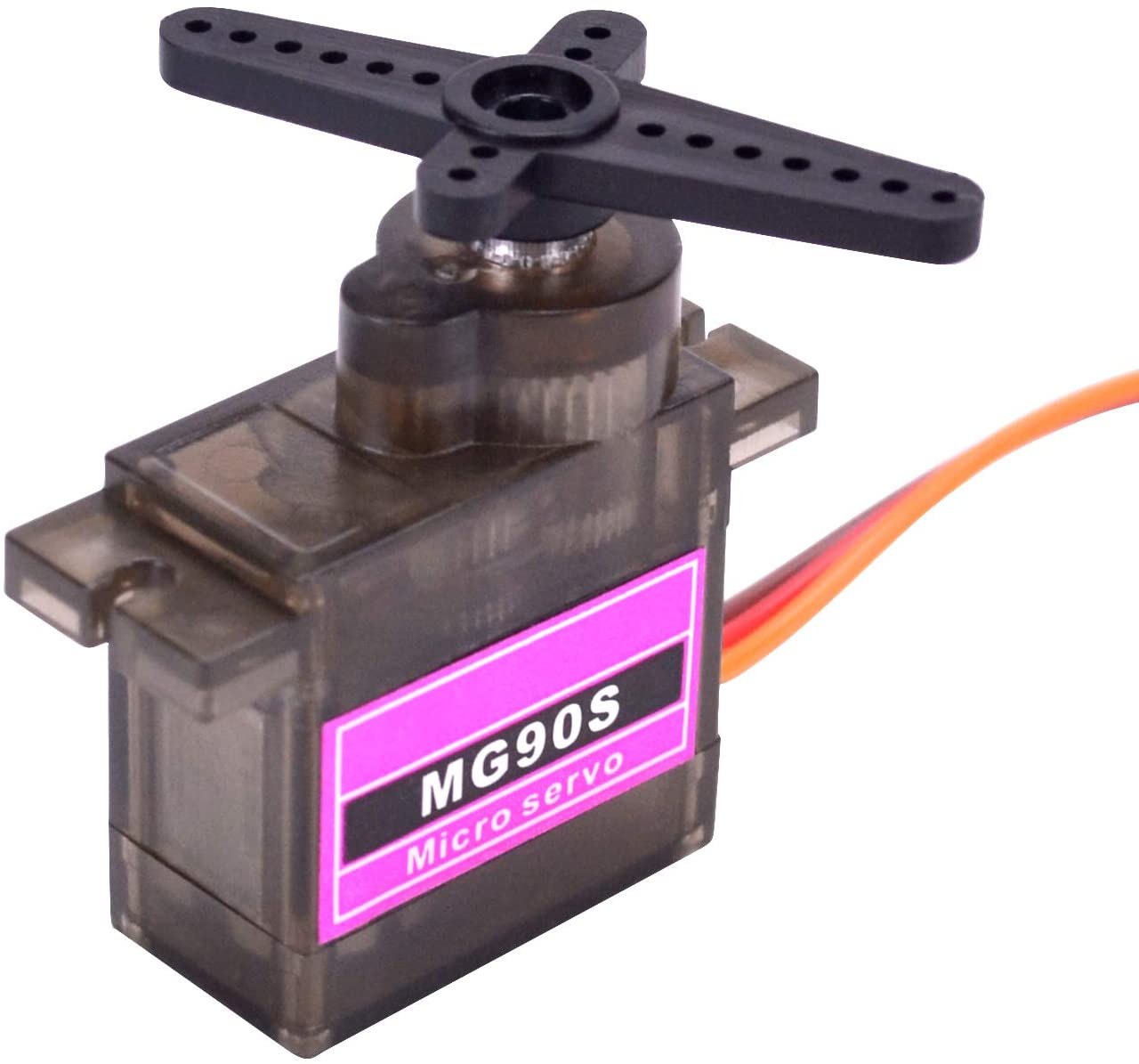
This setup is incredibly versatile. Here are a few practical ways you can use it:
- Robotics: Controlling the pan and tilt of a camera gimbal or the base and arm joints of a small robot.
- Animatronics: Creating lifelike movements for a puppet or animatronic character by independently controlling its head and eyes.
- Model Control: Building a custom controller for RC vehicles or model aircraft to adjust flaps and ailerons precisely.
- Automation: Creating a manual override station for a solar tracker or a multi-axis positioning jig.
Hardware Required
- Arduino Uno (or any compatible board)
- 2x Servo motors (standard 180-degree servos are used here)
- 2x Potentiometers (10kΩ is a common choice)
- Breadboard and jumper wires
- External 5V power supply (recommended for multiple servos)
Wiring Guide
This project requires a bit more wiring than a single-servo setup, mainly because you need to distribute power and ground to multiple components. The key is to use the breadboard's power rails to create a common 5V and GND bus. A wiring diagram is essential for this build.
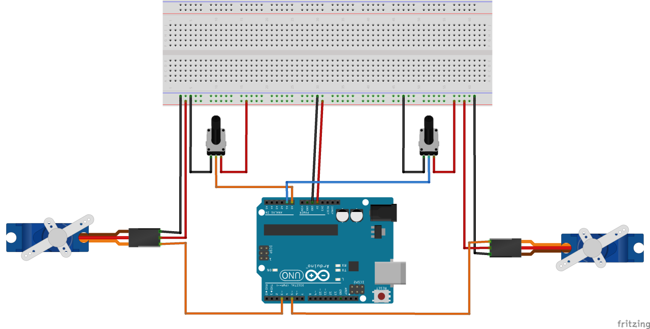
Let's break down the connections, as explained in the video (in video at 02:23). First, set up your power rails: connect the Arduino's 5V pin to the breadboard's positive rail and the GND pin to the negative rail. This gives you easy access to power for all your components.
Potentiometers: Each potentiometer acts as a voltage divider. Connect the right pin of each pot to the 5V rail and the left pin to the GND rail. The middle pin is the "wiper" and provides a variable voltage. Connect the middle pin of the first potentiometer to analog input A0, and the middle pin of the second to A1 (in video at 03:22).
Servo Motors: Each servo has three wires. Connect the dark-colored wire (usually black or brown) to the GND rail. Connect the middle wire (usually red) to the 5V rail. Finally, connect the signal wire (usually orange or yellow) to a PWM-enabled pin on the Arduino. The first servo's signal wire goes to pin 3, and the second servo's signal wire goes to pin 5 (in video at 04:01). Remember, you must use PWM-enabled pins (marked with a tilde "~" on the Uno) for servo control.
Code Explanation
The code is based on the standard "Knob" example from the Arduino IDE but is modified to handle two servos. The logic is straightforward: read the analog value from a potentiometer, map it to an angle, and command the servo to move to that angle. The configuration section at the top of the code is where you'll make all your adjustments.
Here is the user-configurable section that defines the pins and creates the servo objects:
#include <Servo.h>

//**** servo 1 settings
Servo servo1;
const int servo1PotPin = A0;
const int servo1Pin = 3;// Must use PWM enabled pin
int servo1Value;
//**** servo 1 settings END

//**** servo 2 settings
Servo servo2;
const int servo2PotPin = A1;
const int servo2Pin = 5;// Must use PWM enabled pin
int servo2Value;
//**** servo 1 settings END
This is the core of the configuration. To add a third servo, you would copy the "servo 2 settings" block, change all the "2"s to "3", assign a new analog pin (e.g., A2) and a new PWM pin (e.g., 9). The Servo class is built into the Arduino IDE, so no additional libraries are needed.
In the setup() function, the servo.attach(pin) command tells the Arduino which pin is connected to each servo's signal wire. You must have a line for each servo you are using.
void setup() {
  //Robojax.com multiple servo
  servo1.attach(servo1Pin);
  servo2.attach(servo2Pin);
}
In the loop(), the code reads the potentiometer value, maps it to a 0-180 degree range, and writes that angle to the servo. The delay(5) at the end is a tuning parameter. As demonstrated in the video, reducing this value from 15 to 5 milliseconds makes the servo movement much smoother and eliminates vibration (in video at 12:00).
Live Project Demonstration
Once you have the circuit wired and the code uploaded, the demonstration is immediate. When you power the Arduino, each servo will move to a position determined by its corresponding potentiometer's current setting. As you rotate a knob, its servo will smoothly follow the movement. The video demonstrates that the two servos operate entirely independently, allowing for complex, simultaneous movements. If you notice any jitter or vibration, adjusting the delay() value in the loop is the first thing to try.
Chapters
- [00:00] Introduction and Project Overview
- [00:56] Understanding Servo Motors
- [02:23] Wiring Diagram for Two Servos and Potentiometers
- [04:15] Detailed Wiring Explanation
- [06:49] Code Explanation: Configuration and Setup
- [09:15] Code Explanation: Control Logic and Mapping
- [11:15] Live Demonstration and Tuning
Images


/*
 * Control two or more servo motors
 * using potentiometers.
 * Modified by Ahmad Shamshiri on Oct 17, 2019 at 20:13
 * in Ajax, Ontario, Canada . www.Robojax.com
 * This code on robojax https://robojax.com/RJT766
 *
 * Original code from Arduino IDE: File->Examples->Servo->knob
 *
 Controlling a servo position using a potentiometer (variable resistor)
 by Michal Rinott <http://people.interaction-ivrea.it/m.rinott>

 modified on 8 Nov 2013
 by Scott Fitzgerald
 http://www.arduino.cc/en/Tutorial/Knob


 * Get this code and other Arduino codes from Robojax.com


 *  * This code is "AS IS" without warranty or liability. Free to be used as long as you keep this note intact.*
 * This code has been download from Robojax.com
    This program is free software: you can redistribute it and/or modify
    it under the terms of the GNU General Public License as published by
    the Free Software Foundation, either version 3 of the License, or
    (at your option) any later version.

    This program is distributed in the hope that it will be useful,
    but WITHOUT ANY WARRANTY; without even the implied warranty of
    MERCHANTABILITY or FITNESS FOR A PARTICULAR PURPOSE.  See the
    GNU General Public License for more details.

    You should have received a copy of the GNU General Public License
    along with this program.  If not, see <https://www.gnu.org/licenses/>.
 */
#include <Servo.h>

//**** servo 1 settings
Servo servo1;
const int servo1PotPin =A0;
const int servo1Pin = 3;// Must use PWM enabled pin
int servo1Value;
//**** servo 1 settings END

//**** servo 2 settings
Servo servo2;
const int servo2PotPin =A1;
const int servo2Pin = 5;// Must use PWM enabled pin
int servo2Value;
//**** servo 1 settings END

void setup() {
  //Robojax.com multiple servo
  servo1.attach(servo1Pin);
  servo2.attach(servo2Pin);
}

void loop() {
  //Robojax.com multiple servo
  servo1Value = analogRead(servo1PotPin);
  servo1Value = map(servo1Value, 0, 1023, 0, 180);
  servo1.write(servo1Value);

  servo2Value = analogRead(servo2PotPin);
  servo2Value = map(servo2Value, 0, 1023, 0, 180);
  servo2.write(servo2Value);

  delay(5);
 //Robojax.com multiple servo
}// loop end
Things you might need
-
Amazon
-
Amazon
-
eBay
-
AliExpressPurchase SG90 Servo motor 180 or 360 from AliExpresss.click.aliexpress.com
Resources & references
No resources yet.
Files📁
Other files
-
SG90 Servo motor datasheet
robojax-servo-SG90_datasheet.pdf0.12 MB