Lesson 89: Using Continuous or 360 Servo motor| Arduino Step By Step Course
Have you ever wanted to spin a motor in either direction for as long as you want, rather than just sweeping back and forth like a standard servo? This is exactly what a continuous or 360-degree servo motor offers. Unlike a standard servo that moves to a specific angle (typically 0 to 180 degrees), a continuous servo rotates endlessly in either a clockwise or counterclockwise direction. This makes it perfect for building small robots, camera platforms, or any project requiring continuous rotation control.
In this project, we will build a control system for a 360-degree servo using just three push buttons. You will be able to command the servo to rotate clockwise, counterclockwise, or stop at any moment. This guide will walk you through the wiring, explain the user-configurable parts of the code, and show you a live demonstration of the system in action.
Here are a few practical ideas for using a continuous servo in your own projects:
- Build a small two-wheeled robot: Use two continuous servos to drive the wheels, allowing for forward, backward, and turning movements.
- Create a pan-and-tilt camera mount: Use one continuous servo for slow, endless panning of a security or wildlife camera.
- Automate a conveyor belt: Control a small conveyor system for sorting or dispensing items.
- Design a rotating display stand: Showcase a 3D model or product on a platform that spins continuously.
Hardware Required
- Arduino board (Uno, Nano, etc.)
- Continuous (360-degree) servo motor (e.g., FS90R, DS04-NFC)
- 3x Push buttons
- Jumper wires
- Breadboard
Wiring Guide
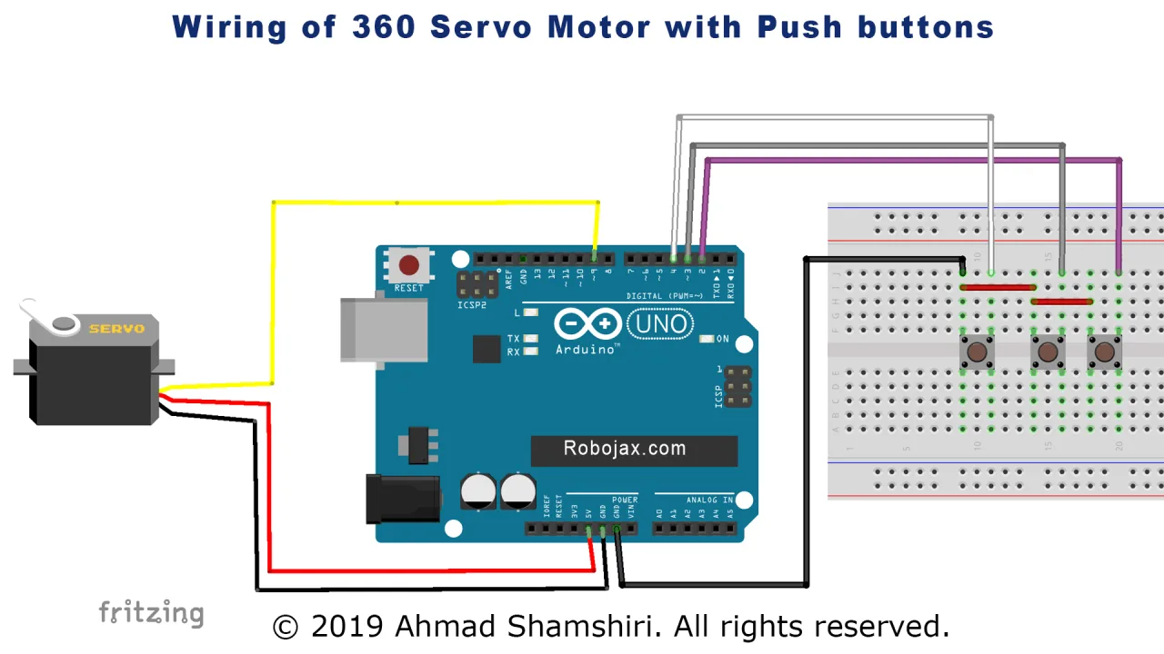
The wiring for this project is straightforward. The servo motor has three wires: typically a dark one for ground (GND), a middle one (often red) for power (5V), and a lighter one (orange, yellow, or white) for the signal. As shown in the video, the servo is wired to the Arduino as follows:
- Servo Ground (dark wire): Connect to Arduino GND.
- Servo Power (middle/red wire): Connect to Arduino 5V.
- Servo Signal (light wire): Connect to Arduino pin 9.
For the three push buttons, each button has two sides. One side of all buttons is connected together and then to the Arduino GND. The other side of each button is connected to a separate digital pin, as described below (in video at 03:40):
- Clockwise (CW) button: Connect to Arduino pin 2.
- Stop button: Connect to Arduino pin 3.
- Counterclockwise (CCW) button: Connect to Arduino pin 4.
Code Explanation
The code is designed to be easily configurable. The most important part you will need to adjust is the sc[] array, which holds the specific PWM values sent to the servo to control its actions. These values are not universal and must be calibrated for your specific servo motor (in video at 12:23).
int sc[]={106, 58, 0};// servo commands are in order
        //CCW, STOP,CW
This array is the heart of the calibration. The values are used in this order:
- sc[0] = 106: This value is sent to make the servo rotate counterclockwise.
- sc[1] = 58: This is the "stop" value. Due to internal circuitry, the exact value that makes the motor stop varies. You may find your servo slowly rotates even when this command is sent, and you will need to adjust this number slightly to find the true "dead stop" value for your motor.
- sc[2] = 0: This value makes the servo rotate clockwise at maximum speed.
You can adjust the values in the sc[] array to change the speed of rotation. For example, setting sc[0] to 70 will make the counterclockwise rotation slower. The closer a value is to the "stop" value (58), the slower the motor will turn in that direction. Values further away from 58 will increase the speed up to a maximum limit.
There are also a few other key variables you may need to modify. The servoPin is set to 9, which must be a PWM-capable pin on your Arduino. The button pins are defined at the top of the code and can be changed if needed.
int servoPin = 9;// this pin must be one of those with PWM ~

#define STOPpin 3 // push button pin  for STOP
#define CWpin 2 //  push button for CW
#define CCWpin 4 // push button for CCW
Finally, the scText[] array holds the strings that are printed to the Serial Monitor for debugging. You can change these if you wish to display different messages.
How to Use the Code
Upload the provided code to your Arduino board. Open the Serial Monitor (set to 9600 baud) to see the status messages. You can now control the servo using the three buttons:
- Press and hold the CW button: The servo will start rotating clockwise. The Serial Monitor will display "CW" and the value being sent.
- Press and hold the CCW button: The servo will start rotating counterclockwise. The Serial Monitor will display "CCW" and the value being sent.
- Press the Stop button: The servo will attempt to stop. The Serial Monitor will display "Stop".
If your servo does not stop completely when the Stop button is pressed, you will need to calibrate the sc[1] value in the sc[] array. Try changing the value slightly (e.g., from 58 to 54 or 52) and re-upload the code until the motor remains perfectly still.
Live Demonstration
In the video, the presenter demonstrates the complete system. You can see the servo rotating in both directions based on the button presses. The Serial Monitor output is also shown, displaying the current state ("CW", "Stop", or "CCW") and the specific value being sent to the servo. This is a great tool for debugging and finding the perfect calibration values for your specific motor. The demonstration also shows how adjusting the values in the sc[] array directly affects the motor's speed, from a slow crawl to its maximum rotation speed.
Conclusion
This project provides a simple and effective way to control a continuous servo motor. By understanding the calibration process for the "stop" value, you can ensure precise control in your own robotics and automation projects.
Video Chapters
- [00:05] Introduction to the Continuous Servo Motor
- [02:02] Hardware Overview of the Servo
- [02:40] Wiring Diagram and Connections
- [05:07] Code Explanation: Variables and Setup
- [08:03] Code Explanation: Main Loop Logic
- [09:56] The servoCommand() Function
- [10:54] Live Demonstration and Serial Monitor Output
- [12:23] Calibrating Servo Speed and Stop Values
Images
++
/*
 *  S05-13 Servo with 3 push buttons
 *  Demonstration of Controlling a Continuous Servo (360 servo)
 *  This code allows you to control a 360-degree servo using push buttons
 *
 * Modified by Ahmad Shamshiri for Robojax Robojax.com
 * on Jan 17, 2019 at 22:42 in Ajax, Ontario, Canada
 Watch the video instruction for this sketch: https://youtu.be/hVe4TSRV4ww

 Watch Introduction to  360 Servo video with code: https://youtu.be/b_xvu6wWafA
 You can get the wiring diagram from my Arduino Course at Udemy.com
 Learn Arduino step by step with all libraries, codes, and wiring diagrams all in one place
 visit my course now http://robojax.com/L/?id=62

 If you found this tutorial helpful, please support me so I can continue creating
 content like this.
 or make a donation using PayPal http://robojax.com/L/?id=64

 Original code by BARRAGAN <http://barraganstudio.com>
 *
 * Code is available at http://robojax.com/learn/arduino

 * This code is "AS IS" without warranty or liability. Free to be used as long as you keep this note intact.
 * This code has been downloaded from Robojax.com
    This program is free software: you can redistribute it and/or modify
    it under the terms of the GNU General Public License as published by
    the Free Software Foundation, either version 3 of the License, or
    (at your option) any later version.

    This program is distributed in the hope that it will be useful,
    but WITHOUT ANY WARRANTY; without even the implied warranty of
    MERCHANTABILITY or FITNESS FOR A PARTICULAR PURPOSE.  See the
    GNU General Public License for more details.

    You should have received a copy of the GNU General Public License
    along with this program.  If not, see <https://www.gnu.org/licenses/>.

*/

#include <Servo.h>

Servo myservo;  // create servo object to control a servo
// twelve servo objects can be created on most boards

int servoPin = 9;// this pin must be one of those with PWM ~


#define STOPpin 3 // push button pin  for STOP
#define CWpin 2 //  push button for CW
#define CCWpin 4 // push button for CCW

int sc[]={106, 58, 0};// servo commands are in order
        //CCW, STOP,CW

String scText[]={"CCW","Stop","CW"};// define texts for 3 actions
int statusText;
int CWBS, CCWBS, SBS;
      //CW button status (CWBS)
      //CCW button status (CCWBS)
      //stop button status (SBS)

void setup() {
  Serial.begin(9600);
  pinMode(STOPpin,INPUT_PULLUP);// set pin for push button STOP
  pinMode(CCWpin,INPUT_PULLUP);// set pin for push button CCW
  pinMode(CWpin,INPUT_PULLUP);// set pin for push button CW

  myservo.attach(servoPin);  // attaches the servo on pin 9 to the servo object
  myservo.write(sc[1]);// send STOP command
  statusText=1;// initial value is STOP
}


void loop() {

    CCWBS = digitalRead(CCWpin);// read status of button CCW
    SBS = digitalRead(STOPpin);// read status of button STOP
    CWBS = digitalRead(CWpin);// read status of button CW

    if(CCWBS ==LOW)
    {
      servoCommand(0);
    }else if(SBS ==LOW)
    {
      servoCommand(1);
    }else if(CWBS ==LOW)
    {
      servoCommand(2);
    }

  Serial.println(scText[statusText]);
  delay(50);
}// loop


void servoCommand(int n)
{
   statusText = n;
   myservo.write(sc[n]);
   Serial.print("Going to  ");
   Serial.print(scText[n]);
   Serial.print( "(");
   Serial.print(sc[n]);
   Serial.println(")");
}
Things you might need
-
Amazon360 Degree Servo motor on Amazonlink.amazon
-
eBay360 Degree Servo motor on eBayebay.us
-
AliExpress360 Degree Servo motor on AliExpresss.click.aliexpress.com
-
AliExpress360 Degree Servo motor on AliExpress-2s.click.aliexpress.com
Resources & references
-
Internal
Files📁
Other files
-
SG90 Servo motor datasheet
robojax-servo-SG90_datasheet.pdf0.12 MB