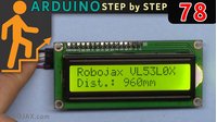
Lesson 78: Display distance from VL53L0X on LCD | Arduino Step By Step Course

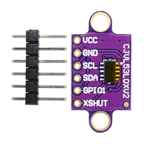
This guide demonstrates how to build a precise laser distance meter using the VL53L0X time-of-flight sensor and a 16x2 LCD display with an I2C module. This project is perfect for makers looking to add accurate, non-contact distance measurement to their creations. The VL53L0X uses a laser to measure distance, making it ideal for applications where ultrasonic sensors might struggle, such as measuring the fill level of a tank or detecting the exact position of an object on a conveyor belt.
Here are a few practical ways you can use this project:
- Automated Pet Feeder: Measure the food level in a container to trigger a refill or send a notification.
- Smart Trash Can: Detect how full the bin is and alert you when it needs to be emptied.
- DIY Height Gauge: Create a precise measuring tool for small objects or to track a child's growth.
- Parking Assistant: Build a sensor system to help with precise parking in a garage or tight space.
- Robotics: Use it in a robot to detect obstacles or measure the distance to a wall for navigation.
Hardware Required
- Arduino Board (e.g., Uno)
- VL53L0X Laser Distance Sensor
- LCD 1602 Display with I2C Module
- Jumper Wires
Wiring Guide
The wiring for this project is straightforward, thanks to the I2C protocol, which allows both the LCD and the sensor to communicate over the same two wires. The VL53L0X sensor requires a 5V power supply, which is drawn directly from the Arduino's 5V pin. To ensure the sensor has a stable power source, an additional pin is used as a secondary VCC. (in video at 00:27)
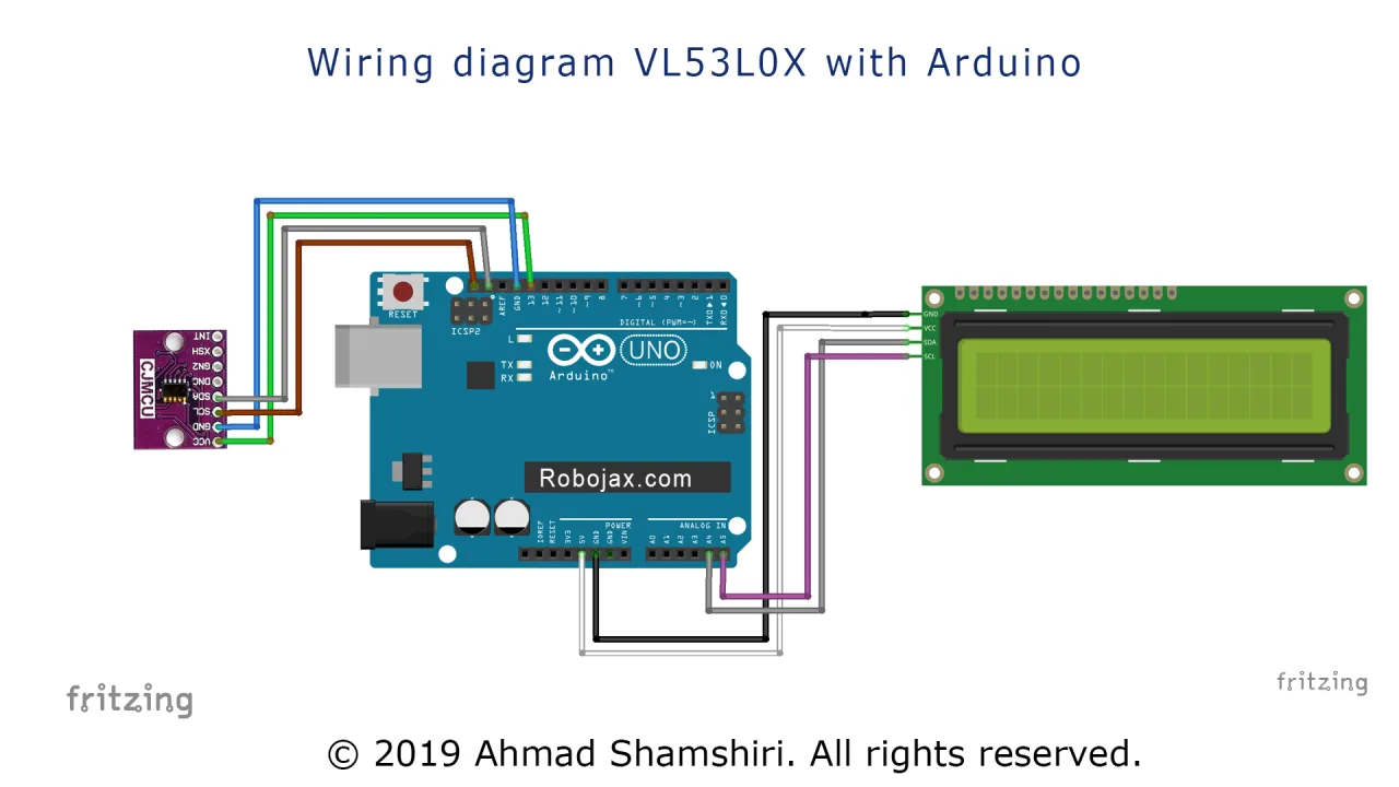
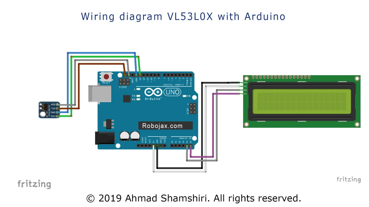
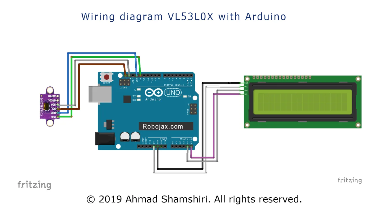
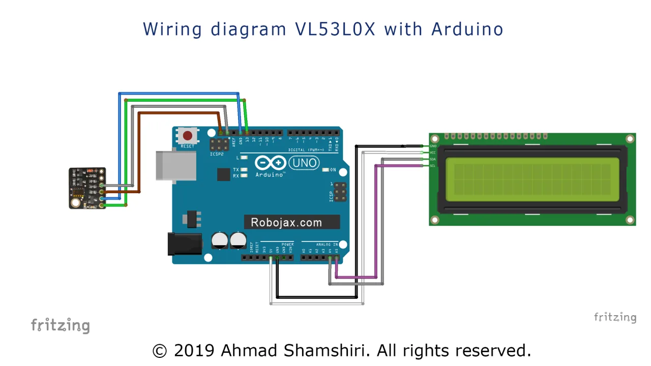
Here is the connection diagram:

The connections are as follows:
- VL53L0X VCC -> Arduino 5V and Pin 13 (Pin 13 is set as a digital output to provide extra power stability).
- VL53L0X GND -> Arduino GND.
- VL53L0X SCL -> Arduino SCL (A5).
- VL53L0X SDA -> Arduino SDA (A4).
- LCD I2C VCC -> Arduino 5V.
- LCD I2C GND -> Arduino GND.
- LCD I2C SCL -> Arduino SCL (A5).
- LCD I2C SDA -> Arduino SDA (A4).
If you are using a different Arduino model, the I2C pins might be located elsewhere. The SDA and SCL pins are often labeled directly on the board. (in video at 02:42)
Code Explanation
The code is designed to be simple to configure. The main user-configurable parts are at the very top of the sketch. (in video at 04:18)
First, we define a constant for the extra power pin. This is used to provide a clean 5V supply to the sensor.
const int vcc2 = 13; // Extra VCC pin for the VL53L0X sensorNext, we create an instance of the LCD library and define its I2C address. You can find this address by running an I2C scanner sketch, as shown in the video. (in video at 03:26)
LiquidCrystal_I2C lcd(0x3F, 16, 2); // Set the LCD address to 0x3F for a 16 chars and 2 line displayFinally, there is a variable that controls the unit of measurement. You can change this value to display the distance in either millimeters or centimeters.
const int type = 1; // Set to 1 for millimeter, 2 for centimeterIn the setup() function, the extra VCC pin is configured as an output and set to HIGH to provide power to the sensor. The LCD is then initialized.
The main logic in the loop() function reads the distance from the sensor, clears the LCD, and prints the value along with the unit. When type is set to 2, the distance is converted from millimeters to a float value in centimeters for a more precise reading. (in video at 06:47)
Live Project Demonstration
In the demonstration, the sensor is tested against a ruler to verify its accuracy. The video shows that the sensor provides very precise readings, with only a few millimeters of deviation. (in video at 08:32)
It is important to note that the sensor has a maximum range of about 1.2 meters in continuous measurement mode. When the target is out of range, the display will show a value of 8190. (in video at 09:53)
Another key observation is that the sensor can give inaccurate readings on highly reflective surfaces. Pointing it at a shiny object can cause significant errors, while pointing it at a matte surface provides accurate results. (in video at 10:42)
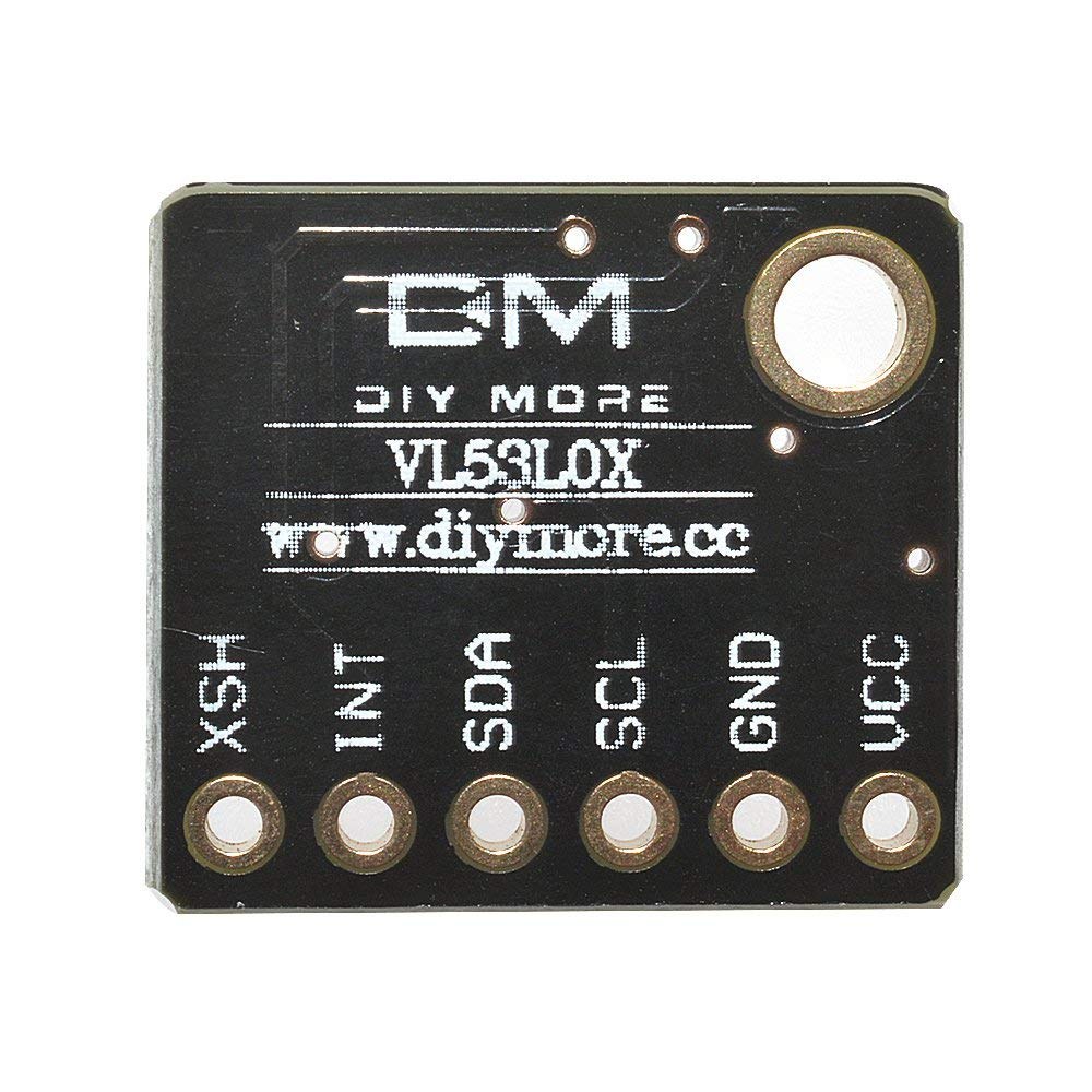
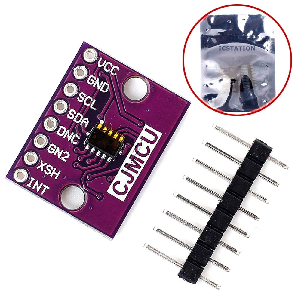
The code is also compatible with different VL53L0X module variants and larger LCDs, such as the 2004 model, without any changes to the wiring. (in video at 11:30)
Video Chapters
- [00:05] Introduction to the VL53L0X and LCD project
- [00:27] Wiring diagram for the VL53L0X and LCD
- [02:51] Detailed wiring on an actual Arduino board
- [03:26] Scanning for the I2C addresses
- [04:18] Code explanation and configuration
- [08:32] Live demonstration of distance measurement
- [09:53] Testing the sensor's range and limitations
- [10:42] Accuracy on different surfaces
- [11:30] Testing with a different sensor module and larger LCD
تصاویر

/*
* Lesson 76-1: Using One single VL6180 Laser Distance Sensor with Arduino
 * Adafruit code modified for this tutorial
 * by Ahmad Shamshiri at 22:22 on
 * March 10-11, 2021 in Ajax, ON, Canada
 Please watch video instruction of this code: https://youtu.be/_H9D0czQpSI

View code for using two or more VL6180X sensors: https://robojax.com/course1/lecture76

  This video is part of Arduino Step by Step Course which starts here: https://youtu.be/-6qSrDUA5a8


If you found this tutorial helpful, please support me so I can continue creating
content like this.

or make a donation using PayPal http://robojax.com/L/?id=64

 * This code is "AS IS" without warranty or liability. Free to be used as long as you keep this note intact. *
 * This code has been downloaded from Robojax.com
    This program is free software: you can redistribute it and/or modify
    it under the terms of the GNU General Public License as published by
    the Free Software Foundation, either version 3 of the License, or
    (at your option) any later version.

    This program is distributed in the hope that it will be useful,
    but WITHOUT ANY WARRANTY; without even the implied warranty of
    MERCHANTABILITY or FITNESS FOR A PARTICULAR PURPOSE.  See the
    GNU General Public License for more details.

    You should have received a copy of the GNU General Public License
    along with this program.  If not, see <https://www.gnu.org/licenses/>.
 */
#include <Wire.h>
#include "Adafruit_VL6180X.h"

Adafruit_VL6180X vl = Adafruit_VL6180X();

void setup() {
  Serial.begin(115200);

  // wait for serial port to open on native usb devices
  while (!Serial) {
    delay(1);
  }

  Serial.println("Adafruit VL6180x test!");
  if (! vl.begin()) {
    Serial.println("Failed to find sensor");
    while (1);
  }
  Serial.println("Sensor found!");
}

void loop() {

  uint8_t range = vl.readRange();
  uint8_t status = vl.readRangeStatus();

  if (status == VL6180X_ERROR_NONE) {
    Serial.print("Range: "); Serial.print(range);
    Serial.println("mm");
  }
//  if(range <=76)
//  {
//    //do something
//  }

  // Some error occurred, print it out!

  if  ((status >= VL6180X_ERROR_SYSERR_1) && (status <= VL6180X_ERROR_SYSERR_5)) {
    Serial.println("System error");
  }
  else if (status == VL6180X_ERROR_ECEFAIL) {
    Serial.println("ECE failure");
  }
  else if (status == VL6180X_ERROR_NOCONVERGE) {
    Serial.println("No convergence");
  }
  else if (status == VL6180X_ERROR_RANGEIGNORE) {
    Serial.println("Ignoring range");
  }
  else if (status == VL6180X_ERROR_SNR) {
    Serial.println("Signal/Noise error");
  }
  else if (status == VL6180X_ERROR_RAWUFLOW) {
    Serial.println("Raw reading underflow");
  }
  else if (status == VL6180X_ERROR_RAWOFLOW) {
    Serial.println("Raw reading overflow");
  }
  else if (status == VL6180X_ERROR_RANGEUFLOW) {
    Serial.println("Range reading underflow");
  }
  else if (status == VL6180X_ERROR_RANGEOFLOW) {
    Serial.println("Range reading overflow");
  }
  delay(50);
}
مواردی که ممکن است به آنها نیاز داشته باشید
-
آمازونخرید VL53L0X از اَمه زونamzn.to
-
ایبیخرید VL53l0x از eBayebay.us
منابع و مراجع
-
خارجیخرید VL53l0x از eBayebay.us
-
خارجی
-
خارجیکتابخانه آرودینو (گیتهاب)github.com
فایلها📁
فایل فریزینگ
-
Adafruit VL6180X Time of Flight Distance SensorFritzing part for the Adafruit VL6180X Time of Flight distance sensor. This sensor measures absolute distance up to 100mm and ambient light, communicating via I2C. Includes the sensor breakout board and pin connections for use in Fritzing projects.
Adafruit VL6180X Time of Flight Distance Sensor-1.fzpz0.02 MB