ESP32 Tutorial 6/55 - Using RGB LED Project 2.3 -SunFounder's ESP32 IoT Learning kit
In this tutorial, we will learn how to control an RGB LED using the ESP32 microcontroller. This project will help you understand how to connect the RGB LED and control its colors using PWM (Pulse Width Modulation) signals. By the end of this tutorial, you will be able to create any color combination by adjusting the intensity of each LED component. This is a fundamental skill for creating visually engaging projects.

To get a better understanding of the RGB LED and its color mixing capabilities, we will explore the wiring and the code needed to control it with the ESP32. If you need visual assistance, be sure to check the video at (in video at 03:20) for a clearer explanation of the wiring and code setup.
Hardware Explained
The main components of this project include the ESP32 module, the RGB LED, and resistors. The ESP32 is a powerful microcontroller that features built-in Wi-Fi and Bluetooth, making it ideal for IoT applications. The RGB LED consists of three individual LEDs (red, green, and blue) housed within a single package, allowing for a wide range of colors based on the combination of the three colors.
In our setup, the RGB LED will be wired in a common anode configuration, where the anode pin is connected to a positive voltage, and each color's cathode pin is controlled independently. This way, we can adjust the brightness of each color by sending PWM signals through the ESP32.
Datasheet Details
| Manufacturer | SunFounder |
|---|---|
| Part number | RGB-LED-4PIN |
| Common Type | Common anode |
| Forward Voltage (per LED) | 2.0 V (Red), 3.2 V (Green), 3.2 V (Blue) |
| Max Current (per LED) | 20 mA |
| Operating Temperature | -25 to 85 °C |
| Package | 4-Pin Through-hole |
- Use a 220 Ω resistor for each color to limit current and prevent damage.
- Ensure the common pin is connected to the appropriate voltage (3.3 V for ESP32).
- Double-check polarity when connecting the RGB LED to avoid reverse damage.
- Use PWM to control brightness levels, with a frequency around 5000 Hz recommended.
- Test each color individually before wiring the entire setup.
Wiring Instructions
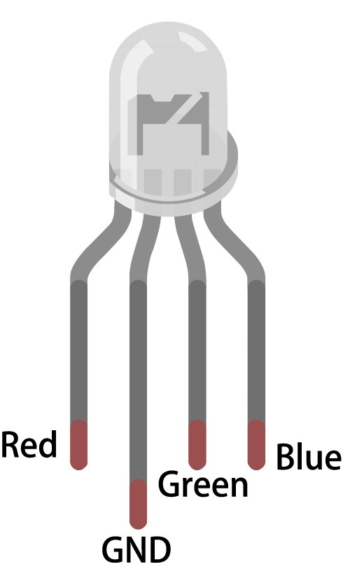
To wire the RGB LED to the ESP32, start by identifying the pins on the RGB LED. The longest pin is the common anode, which will connect to the 3.3 V supply on the ESP32. The other three pins are for red, green, and blue. In our setup, connect the red pin to GPIO 27, the green pin to GPIO 26, and the blue pin to GPIO 25. Each of these pins will also have a 220 Ω resistor connected to them.
Begin by placing the RGB LED on the breadboard, ensuring the common anode pin is on the left. Insert the red pin into the breadboard and connect it to one end of the resistor, with the other end of the resistor going to GPIO 27. Repeat this for the green and blue pins, connecting the green pin to GPIO 26 and the blue pin to GPIO 25. Finally, connect the common pin to the 3.3 V pin on the ESP32 to complete the circuit. Make sure to connect the ground of the ESP32 to the breadboard as well.

Code Examples & Walkthrough
In the code, we start by defining the RGB LED pins using constants. For example, const int redPin = 27; defines the GPIO pin for the red LED. We also set the PWM frequency and resolution with const int freq = 5000; and const int resolution = 8;. This sets up the necessary parameters for controlling the brightness of each LED color.
const int redPin = 27;
const int greenPin = 26;
const int bluePin = 25;
Next, we configure the PWM channels for each color in the setup() function. The ledcAttach() function links each pin to the corresponding PWM channel. This setup ensures that we can control the brightness of each color independently.
void setup() {
  ledcAttach(redPin, freq, resolution);
  ledcAttach(greenPin, freq, resolution);
  ledcAttach(bluePin, freq, resolution);
}
In the loop() function, we use the setColor() function to change the LED colors. The values passed to this function represent the intensity of red, green, and blue. For instance, calling setColor(255, 0, 0); sets the LED to red. After each color change, we use delay(1000); to wait for one second before switching to the next color.
void loop() {
  setColor(255, 0, 0); // Red
  delay(1000);
  setColor(0, 255, 0); // Green
  delay(1000);
}
Demonstration / What to Expect
After completing the wiring and uploading the code to the ESP32, you should see the RGB LED cycle through various colors: red, green, blue, yellow, purple, and cyan. If the LED does not light up correctly, double-check your wiring and ensure that the common anode is connected to 3.3 V. Additionally, if you notice any unexpected colors, verify the resistor connections to the LED pins.
As demonstrated in the video (in video at 10:45), adjusting the values in the setColor() function allows you to create different colors. Experiment with various combinations to see how the RGB LED responds.
Video Timestamps
- 00:00 - Introduction to RGB LED
- 03:20 - Wiring explanation
- 10:45 - Code walk-through
- 12:30 - Demonstration of color mixing
图像
This code has not been parsed yet. Please return to the admin panel to parse it.Common Course Links
Common Course Files
资源与参考
-
文档ESP32 教程 6/55 - SunFounder RGB LED 文档页面docs.sunfounder.com
文件📁
没有可用的文件。