In this tutorial, we will learn how to use a push button to toggle an LED on and off with an ESP32 microcontroller. The project will demonstrate how to read the state of the push button and control the LED accordingly. When the button is pressed, the LED will turn on, and when released, it will turn off. This is a foundational concept for many interactive projects using the ESP32.
The ESP32 is a powerful microcontroller with built-in Wi-Fi and Bluetooth capabilities, making it suitable for various IoT applications. In this lesson, we will use the ESP32 from the SunFounder ESP32 Starter Kit, which includes essential components like resistors and LEDs, to create a simple circuit. For a detailed explanation of the wiring and code, please refer to the video (in video at 00:00).
Hardware Explained
The key components for this project include the ESP32 microcontroller, a push button, an LED, and resistors. The ESP32 acts as the brain of the project, controlling the LED based on the push button's state. The push button allows users to interact with the circuit, while the LED provides visual feedback when the button is pressed.
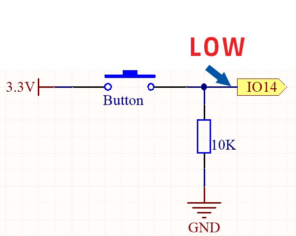
The push button works by closing the circuit when pressed, allowing current to flow. This action sends a HIGH signal to the designated input pin of the ESP32, which can then be read in the code. The resistor connected to the button ensures that the pin has a defined state when the button is not pressed, preventing erratic behavior.
Push button with resistor
Wiring Instructions
To wire the circuit, start by connecting the longer pin of the LED (anode) to a 220-ohm resistor. Connect the other end of the resistor to GPIO pin 26 on the ESP32. The shorter pin of the LED (cathode) should be connected to the ground. Next, take the push button and connect one side to the 3.3V power supply on the board. The other side of the push button connects to GPIO pin 14.
Push button without resistor
Push button without resistor
Push button with resistor
Push button with resistor
Additionally, place a 10k-ohm resistor from GPIO pin 14 to ground to ensure the pin reads LOW when the button is not pressed. Finally, connect the ground wire from the ESP32 to the common ground on the breadboard. This setup will allow the ESP32 to read the button state and control the LED accordingly.
Code Examples & Walkthrough
The core of the program starts by defining the pin numbers for the button and the LED using constants. This ensures that the pin assignments remain unchanged throughout the execution of the program.
// set pin numbers
const int buttonPin = 14;  // Button pin
const int ledPin = 26;     // LED pin
In the setup() function, we initialize the serial monitor and set the button pin as an input while configuring the LED pin as an output. This prepares the ESP32 to read from the button and control the LED.
Inside the loop() function, the program continuously reads the button state and prints it to the serial monitor. If the button is pressed, the LED is turned on; otherwise, it is turned off. This logic is essential for toggling the LED based on the button's state.
This basic functionality allows the LED to respond directly to the push button. For further details on the project and the complete code, please refer to the video provided (in video at 14:00).
Demonstration / What to Expect
Once the wiring is complete and the code is uploaded, pressing the push button should turn the LED on, and releasing it will turn the LED off. This behavior confirms that the button state is being read correctly. If the LED does not respond as expected, check the wiring and ensure that the button is functioning properly.
During testing, make sure to observe the serial monitor for the button state readings. You should see a '1' when the button is pressed and a '0' when it is released. If the readings fluctuate unexpectedly, it may indicate a wiring issue or a need for additional debouncing logic in the code.