ESP32 Tutorial 17/55 - Controlling Servo Motor using ESP32 and Potentiometer -ESP32 IoT Learning kit
In this tutorial, we will learn how to control a servo motor using an ESP32 microcontroller and a potentiometer from the ESP32 IoT Learning kit by SunFounder. By the end of this project, you will be able to adjust the angle of the servo motor smoothly using the potentiometer, allowing for precise control. This is a great way to explore the capabilities of the ESP32 and how it interfaces with motors.

As we dive into the details, we will cover the necessary hardware components, wiring instructions, and code examples to get everything up and running. For a more visual representation, be sure to check out the video associated with this tutorial (in video at 0:30).
Hardware Explained
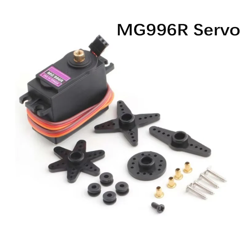
The primary components for this project include the ESP32 microcontroller, a servo motor (SG90), and a potentiometer. The ESP32 is a powerful microcontroller that offers built-in Wi-Fi and Bluetooth, making it suitable for IoT projects. It is capable of controlling various devices, including motors, with high precision.
The SG90 servo motor is a widely-used component that can rotate approximately 270 degrees. It operates on a pulse-width modulation (PWM) signal, where the angle of rotation is determined by the width of the pulse sent to it. The potentiometer acts as a variable resistor, allowing you to adjust the voltage sent to the ESP32, which in turn controls the servo's position.
Datasheet Details
| Manufacturer | SG |
|---|---|
| Part number | SG90 |
| Logic/IO voltage | 3.3 V (ESP32) |
| Supply voltage | 5 V |
| Output current (per channel) | 1.2 A |
| Peak current (per channel) | 2.5 A |
| PWM frequency guidance | 50 Hz |
| Input logic thresholds | 0.2 V (low), 2.5 V (high) |
| Voltage drop / RDS(on) / saturation | 0.5 V |
| Thermal limits | 85 °C max |
| Package | Plastic |
| Notes / variants | Available in different gear types |
- Ensure the servo is powered with a suitable voltage (5V).
- Connect the ground of the servo to the ESP32 ground for a common reference.
- Use appropriate PWM signals to control the servo's position.
- Be aware of the servo's current requirements; use an external power supply if necessary.
- Check for correct pin assignments when wiring to avoid misconfigurations.
Wiring Instructions

To wire the servo motor and potentiometer to the ESP32, start by connecting the ground wire of the servo (typically black or brown) to one of the ground pins on the ESP32. Next, connect the power wire (typically red) of the servo to the 5V pin on the ESP32. Finally, connect the signal wire (typically orange or white) from the servo to pin 25 on the ESP32.
For the potentiometer, connect one outer pin to the 3.3V pin on the ESP32 and the other outer pin to ground. The middle pin of the potentiometer should be connected to pin 34 on the ESP32. This setup allows the ESP32 to read the varying voltage output from the potentiometer, which will be used to control the servo's position.
Code Examples & Walkthrough
The following code snippet initializes the servo and sets the parameters for controlling its movement:
#include

Servo myServo;
const int servoPin = 25;
const int minPulseWidth = 500; // 0.5 ms
const int maxPulseWidth = 2500; // 2.5 ms

void setup() {
  myServo.attach(servoPin, minPulseWidth, maxPulseWidth);
  myServo.setPeriodHertz(50); // Standard 50Hz servo
}
In this code, we include the ESP32Servo library and create an instance of the servo with the name myServo. We define the pin number for the servo and set the minimum and maximum pulse widths that correspond to the servo's angle limits.

Next, let's take a look at the loop that continuously moves the servo back and forth:
void loop() {
  for (int angle = 0; angle <= 180; angle++) {
    int pulseWidth = map(angle, 0, 180, minPulseWidth, maxPulseWidth);
    myServo.writeMicroseconds(pulseWidth);
    delay(15);
  }
  for (int angle = 180; angle >= 0; angle--) {
    int pulseWidth = map(angle, 0, 180, minPulseWidth, maxPulseWidth);
    myServo.writeMicroseconds(pulseWidth);
    delay(15);
  }
}
This loop gradually changes the angle from 0 to 180 degrees and back again, using the map function to convert the angle into the corresponding pulse width for the servo. Each change is followed by a short delay to allow the servo to reach its new position smoothly.
Demonstration / What to Expect
Once everything is wired and the code is uploaded, you should see the servo motor moving smoothly from 0 to 180 degrees and back. If you adjust the potentiometer, the servo should reflect the new position based on the voltage provided by the potentiometer. Be cautious of reversed polarity when wiring, as it may damage your components (in video at 3:45).
Video Timestamps
- 00:00 Start
- 1:56 What's a servo motor
- 5:00 Docs page
- 6:33 Wiring for servo explained
- 7:45 Selecting COMP port for ESP32 in Arduino IDE
- 9:27 Arduino code explained
- 14:31 Demonstration of servo control using ESP32
- 16:04 Powering servo other than 5V
- 18:47 Controlling Servo without the loop
- 20:15 Controlling Servo with Potentiometer
- 21:37 Servo with pot Arduino code explained
图像
This code has not been parsed yet. Please return to the admin panel to parse it.Common Course Links
Common Course Files
资源与参考
-
文档ESP32教程 17/55- SunFunder伺服电机文档docs.sunfounder.com
文件📁
数据手册 (pdf)
-
DS5160伺服电机数据表
DS5160_datasheet.pdf0.33 MB
其他文件
-
Download SG90 datasheet (PDF)
robojax-servo-sg90_datasheet.pdf


![Micro with Headers [A000053] - ATmega32U4 Microcontroller, 16MHz, 20 Digital ...](https://i.ebayimg.com/images/g/5mQAAeSwV5dp0cpF/s-l225.jpg)