ESP32 Tutorial 15/55 - DC Motor Speed Control with ESP32 L293D | SunFounder's ESP32 IoT Learning kit
ESP32 Tutorial 15/55 - DC Motor Speed Control with ESP32 L293D | SunFounder's ESP32 IoT Learning kit
Controlling a DC motor with an ESP32 can seem daunting, but it is quite manageable with the right components and understanding. In this tutorial, we will build a project that allows us to control the speed and direction of a DC motor using the L293D motor driver. By the end, you will have a working setup that can rotate the motor forwards and backwards while adjusting its speed. For a visual reference, make sure to check the video at (in video at 00:00).
Hardware Explained
The main components of this project include the ESP32 microcontroller and the L293D motor driver. The ESP32 is a powerful microcontroller with built-in Wi-Fi and Bluetooth capabilities, making it suitable for IoT applications. It can control various hardware components, including motors, through its GPIO pins. The L293D is a dual H-bridge motor driver that allows you to control the direction and speed of two DC motors. Each H-bridge can drive a motor in either direction by reversing the polarity of the voltage applied to the motor terminals. Additionally, the L293D can handle a current of up to 600 mA per channel, making it suitable for small to medium-sized motors.

Datasheet Details
| Manufacturer | Texas Instruments |
|---|---|
| Part number | L293D |
| Logic/IO voltage | 2.5 – 7 V |
| Supply voltage | 4.5 – 36 V |
| Output current (per channel) | 600 mA (typ.) |
| Peak current (per channel) | 1.2 A (max) |
| PWM frequency guidance | 20 kHz (typ.) |
| Input logic thresholds | 0.8 V (high), 2.0 V (low) |
| Voltage drop / RDS(on) / saturation | 1.5 V (max) |
| Thermal limits | 150 °C (max) |
| Package | 16-DIP |
| Notes / variants | Quadruple half-H driver |
- Ensure proper heat sinking for high current applications.
- Decouple the power supply with capacitors to prevent voltage spikes.
- Be cautious with wiring to prevent reversed polarity.
- Use PWM for speed control to avoid overheating.
- Check the motor's rated voltage to prevent damage.
Wiring Instructions

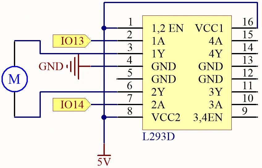
To wire the ESP32 and the L293D motor driver, start by connecting the power. Connect pin 16 of the L293D to the positive terminal of your power supply, and pin 4 to ground. Next, connect the motor: one terminal to pin 3 and the other to pin 6 on the L293D. For control signals, connect the ESP32's GPIO pin 13 to pin 2 on the L293D and GPIO pin 14 to pin 7. Finally, make sure to connect the ESP32's ground to the L293D ground to ensure a common reference. If the video mentions alternative wiring (in video at 05:00), make sure to follow the specific changes shown.
Code Examples & Walkthrough
The code for controlling the motor consists of defining the pins for the motor and setting their modes. Here’s an excerpt from the setup function:
#define motor1A 13
#define motor2A 14

void setup() {
  pinMode(motor1A, OUTPUT);
  pinMode(motor2A, OUTPUT);
}
In this snippet, we define the motor control pins as constants and set them as outputs in the setup function. This is crucial as it prepares the pins for controlling the motor. The loop function is where the motor's behavior is controlled. Here’s a key part of the loop:
void loop() {
  digitalWrite(motor1A, HIGH);
  digitalWrite(motor2A, LOW);
  delay(2000);

  digitalWrite(motor1A, LOW);
  digitalWrite(motor2A, HIGH);
  delay(2000);

  digitalWrite(motor1A, LOW);
  digitalWrite(motor2A, LOW);
  delay(3000);
}
This code rotates the motor in one direction for 2 seconds, then reverses the direction for another 2 seconds, and finally stops the motor for 3 seconds. This loop will repeat indefinitely, allowing for continuous control. For more detailed insights and the complete code, refer to the full program that loads below the article.
Demonstration / What to Expect
Upon successfully wiring and uploading the code, you should see the motor rotate in one direction for 2 seconds, change direction for another 2 seconds, and then stop for 3 seconds. If the motor does not respond as expected, check for common pitfalls such as reversed polarity or incorrect pin connections (in video at 08:00). This setup provides a straightforward way to control the speed and direction of a DC motor using the ESP32 and L293D.
Video Timestamps
- 00:00 Start
- 2:01 Introduction to DC motor
- 6:14 L293D Motor driver
- 9:17 Project Docs.
- 11:04 Wiring Explained
- 14:41 Arduino Motor control with ESP32
- 17:10 Selecting Arduino Ports for ESP32 board
- 18:52 Project demonstration
- 22:08 Motor Speed Control using ESP32
- 26:22 Speed Control Demo
- 28:01 Speed and Direction control Arduino code
- 29:05 Demonstration of Speed and Direction
图像
This code has not been parsed yet. Please return to the admin panel to parse it.Common Course Links
Common Course Files
|||您可能需要的东西
-
亚马逊购买 L293D 电机驱动 ICamzn.to
-
易趣从eBay购买一枚L293D芯片。ebay.us
-
全球速卖通从AliExpress购买L293D电机驱动ICs.click.aliexpress.com
资源与参考
-
文档ESP32 教程 15/55 - SunFounder 电机控制文档docs.sunfounder.com
文件📁
数据手册 (pdf)
-
L293d_四重半桥数据表
l293d_Quadruple_half_bridge_datasheet.pdf0.34 MB