ESP32 Tutorial 27/55 - Measuring Distanc with Ultrasonic Sensor | SunFounder's ESP32 IoT Learning kit
In this tutorial, we will learn how to use an ultrasonic distance sensor with the ESP32 to measure distances and display the results on a screen. We will also explore how to activate a buzzer when an object is detected within a specific range. This project highlights the versatility of the ESP32 microcontroller, which integrates Wi-Fi and Bluetooth capabilities, making it suitable for various IoT applications.
Throughout this guide, you will find explanations of the hardware components, wiring instructions, and code snippets to help you implement the project successfully. For additional clarity, please refer to the video (in video at 00:00).
Hardware Explained
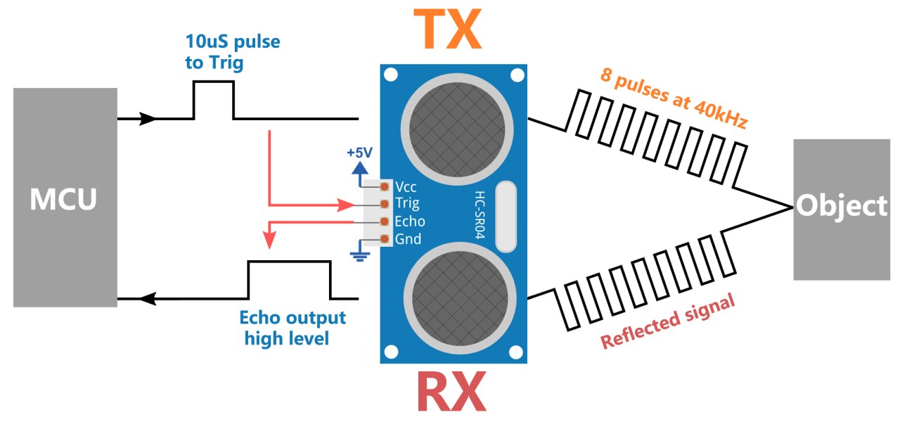
The primary components of this project include the ESP32 microcontroller, the ultrasonic sensor (HC-SR04), and a buzzer. The ultrasonic sensor consists of two main parts: a transmitter that emits ultrasonic waves and a receiver that listens for the reflected waves. By measuring the time it takes for the waves to return, we can calculate the distance to an object.
The ESP32 serves as the central controller, processing data from the ultrasonic sensor and controlling the buzzer based on the measured distance. The buzzer will sound when the detected distance is less than a defined threshold, indicating that an object is too close.
Datasheet Details
| Manufacturer | HC-SR04 |
|---|---|
| Part number | HC-SR04 |
| Logic/IO voltage | 5 V |
| Supply voltage | 5 V |
| Output current (per channel) | 16 mA |
| Peak current (per channel) | … |
| PWM frequency guidance | … |
| Input logic thresholds | … |
| Voltage drop / RDS(on) / saturation | … |
| Thermal limits | … |
| Package | … |
| Notes / variants | Measuring range: 2 cm to 400 cm |
- Ensure proper power supply of 5 V for the sensor.
- Maintain a clear path for ultrasonic waves to avoid interference.
- Use short wires to minimize signal delay and noise.
- Ensure correct pin connections to avoid miscommunication.
- Test the sensor in various environments to check for accuracy.
Wiring Instructions

To wire the ultrasonic sensor to the ESP32, connect the VCC pin of the sensor to the 5V pin on the ESP32. Next, connect the GND pin of the sensor to one of the ground (GND) pins on the ESP32. The trigger pin (Trig) from the sensor should be connected to GPIO 26 on the ESP32, while the echo pin (Echo) should be connected to GPIO 25. This setup allows the ESP32 to send a signal to the sensor and receive the echo signal to calculate distance.

For the buzzer, connect the positive (long) leg to GPIO 12 on the ESP32 and the negative (short) leg to the GND. Ensure that all connections are secure to prevent any loose wiring during operation. If using a breadboard, align the buzzer connections properly to avoid miswiring. Make sure to refer to the video for wiring confirmation (in video at 05:12).
Code Examples & Walkthrough
The code initializes the pins for the ultrasonic sensor and sets up serial communication. The main function, readSensorData(), is responsible for sending a trigger signal and measuring the response time from the echo pin.
const int echoPin = 25;
const int trigPin = 26;

void setup() {
  Serial.begin(115200);
  pinMode(echoPin, INPUT);
  pinMode(trigPin, OUTPUT);
  Serial.println("Ultrasonic sensor:");
}
The code defines echoPin and trigPin as constants for the pins connected to the ultrasonic sensor. In the setup() function, we initialize serial communication and set the pin modes accordingly.
float readSensorData() {
  digitalWrite(trigPin, LOW);
  delayMicroseconds(2);
  digitalWrite(trigPin, HIGH);
  delayMicroseconds(10);
  digitalWrite(trigPin, LOW);

  unsigned long microsecond = pulseIn(echoPin, HIGH);
  float distance = microsecond / 29.00 / 2;
  return distance;
}
This excerpt shows the readSensorData() function, which sends a 10-microsecond pulse to the trigger pin. It then measures the time taken for the echo pin to receive the signal back, calculates the distance, and returns this value.
Finally, the loop function continuously reads the distance and prints it to the serial monitor. If the distance is below 20 cm, the buzzer will be activated.
Demonstration / What to Expect
When you run the program, the ESP32 will display the measured distance in centimeters on the serial monitor. If an object enters within 20 cm of the sensor, the buzzer will sound. This behavior can be tested by placing objects at various distances in front of the sensor. Be cautious of reversed polarity and ensure that the connections are made as specified to avoid any issues during operation (in video at 08:00).
Video Timestamps
- 00:00 Start
- 1:46 Introduction to Ultrasonic Sensor
- 6:02 Wiring explained
- 7:37 ESP32 Arduino code explained
- 11:33 Selecting ESP32 board and COM port in Arduino IDE
- 13:15 Demonstration of measuring distance
- 16:43 Tacking action with distance: buzzer
图像
This code has not been parsed yet. Please return to the admin panel to parse it.Common Course Links
Common Course Files
|||您可能需要的东西
-
易趣从eBay购买HC-SR04超声波传感器ebay.us
-
Banggood从Banggood购买HC-SR04超声波传感器banggood.com
资源与参考
-
文档ESP32 教程 27/55 - SunFounder 超声波距离传感器文档页面docs.sunfounder.com
-
外部Arduino官方网站上的HC-SR04超声波库playground.arduino.cc
文件📁
没有可用的文件。