ESP32 Tutorial 34/55 - Color gradient with RGB LED and Knob | SunFounder's ESP32 IoT Learning kit
In this tutorial, we will create a color gradient effect using an RGB LED that adjusts based on the position of a potentiometer (knob). The project utilizes an ESP32 microcontroller, which provides built-in Wi-Fi and Bluetooth capabilities, making it a versatile choice for IoT projects. By turning the potentiometer, we can smoothly transition between different colors, demonstrating both the functionality of the RGB LED and the ability to read analog values from the potentiometer.

This project is ideal for learning about PWM (Pulse Width Modulation) and how to control analog devices with a microcontroller. Throughout this tutorial, we will discuss the necessary hardware components, wiring instructions, and provide code snippets to help you implement the project. For a more visual explanation, be sure to check out the associated video (in video at 02:15).
Hardware Explained

The main components used in this project include the ESP32 microcontroller, an RGB LED, and a potentiometer. The ESP32 is a powerful microcontroller that can handle various tasks, including wireless communication, making it suitable for IoT applications. The RGB LED consists of three individual LEDs (red, green, and blue) that can be mixed to produce a wide range of colors. The potentiometer acts as an adjustable resistor that provides a variable voltage output based on its position.
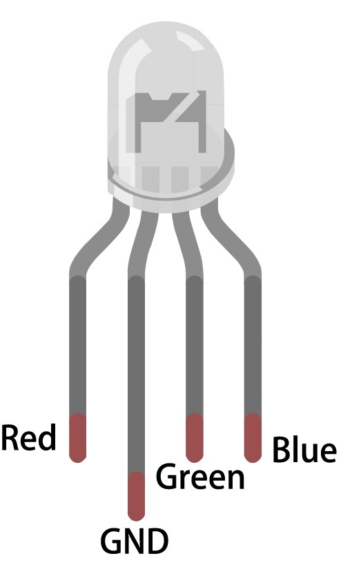
The RGB LED can be connected in two configurations: common anode or common cathode. In this project, we will use a common anode configuration, where all anodes are connected together to a positive voltage, allowing us to control the brightness of each LED individually with PWM. The potentiometer will be connected to an analog input on the ESP32 to read its position and adjust the RGB values accordingly.
Datasheet Details
| Manufacturer | SunFounder |
|---|---|
| Part number | RGB LED |
| Logic/IO voltage | 3.3 V |
| Supply voltage | 5 V |
| Output current (per channel) | 20 mA |
| Peak current (per channel) | 30 mA |
| PWM frequency guidance | 5 kHz |
| Input logic thresholds | 0.3 V (low) / 2.7 V (high) |
| Voltage drop / RDS(on) / saturation | 1.8 V (typ.) |
| Thermal limits | Operating temperature: -40°C to +85°C |
| Package | Through-hole |
| Notes / variants | Common anode configuration |
- Use a 220 Ohm resistor for each LED channel to limit current.
- Ensure proper power supply voltage (5V) for the RGB LED.
- Connect the common anode to the positive voltage supply.
- Use PWM for controlling the brightness of each LED color.
- Be cautious with the potentiometer's connection to avoid floating inputs.
- Verify that the ESP32 is correctly powered before uploading code.
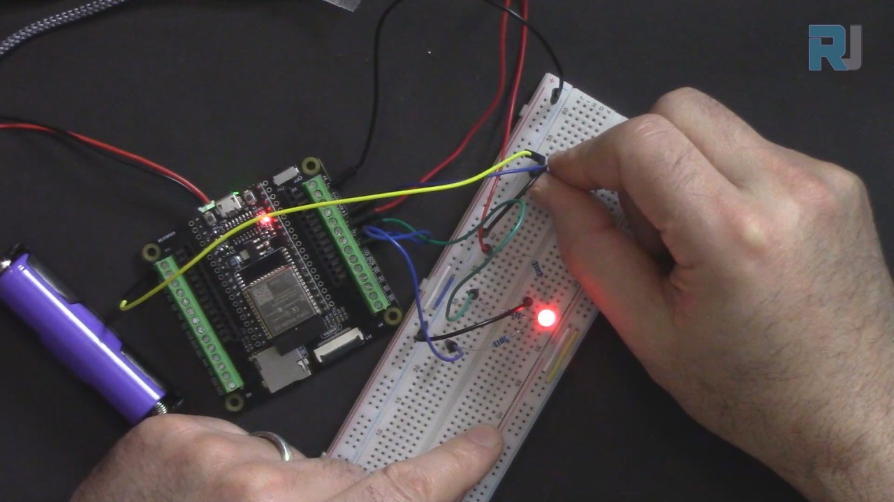
Wiring Instructions
To wire the RGB LED and potentiometer to the ESP32, start by connecting the common anode pin of the RGB LED to the 3.3V power pin on the ESP32. The red, green, and blue pins of the RGB LED will connect to pins 27, 26, and 25 respectively. Make sure to place a 220 Ohm resistor in series with each LED color pin to limit the current and protect the LED.
Next, connect the potentiometer to the ESP32 by linking the left pin to the 3.3V power pin, the right pin to ground, and the middle pin to 14 on the ESP32. This configuration allows the ESP32 to read the analog voltage from the potentiometer, which will be used to adjust the color of the RGB LED based on its position.
Code Examples & Walkthrough
In the setup function, we define the pins for the RGB LED and the potentiometer, as well as initialize the PWM settings. The following code snippet shows how we set up the RGB LED pins:
const int redPin = 27;
const int greenPin = 26;
const int bluePin = 25;

void setup() {
  ledcAttach(redPin, freq, resolution);
  ledcAttach(greenPin, freq, resolution);
  ledcAttach(bluePin, freq, resolution);
}
In this snippet, we define the pins for the red, green, and blue LEDs, and attach them to PWM channels with a defined frequency and resolution.
The loop function reads the potentiometer's value and converts it to a hue value, which is then used to determine the RGB values. The following excerpt demonstrates this process:
void loop() {
  int knobValue = analogRead(KNOB_PIN);
  float hueValue = (float)knobValue / 4095.0;
  int hue = (int)(hueValue * 360);

  int red, green, blue;
  HUEtoRGB(hue, &red, &green, &blue);
  setColor(red, green, blue);
}
This code reads the analog value from the potentiometer, normalizes it, and calculates the corresponding hue. It then calls the HUEtoRGB function to convert the hue into RGB values, which are passed to the setColor function to update the LED.
Demonstration / What to Expect
Upon completing the wiring and uploading the code, you should be able to turn the potentiometer to change the color of the RGB LED smoothly. As you rotate the knob, the LED will transition through various colors based on the hue value calculated from the knob position. If the LED does not light up or behaves unexpectedly, check the wiring and ensure that the potentiometer is connected correctly (in video at 10:45).
Video Timestamps
- 00:00 Start
- 2:11 Introduction to the project
- 4:31 RGB LED
- 8:18 RGB Color
- 12:18 Wiring explained
- 17:59 Arduino Code explained
- 24:12 Selecting ESP32 Board and COM port in Arduino IDE
- 25:54 Demonstration
图像


This code has not been parsed yet. Please return to the admin panel to parse it.Common Course Links
Common Course Files
资源与参考
-
文档ESP32教程 34/55 - SunFounder颜色渐变文档页面docs.sunfounder.com
文件📁
没有可用的文件。