In this tutorial, we will create a digital dice using a seven-segment display and the ESP32 from SunFounder's IoT learning kit. The project will allow you to roll a virtual dice, generating numbers from 1 to 6 at the press of a button. This is a fantastic way to explore the capabilities of the ESP32 while learning about interfacing with displays and buttons. For additional clarity, be sure to check the video at (in video at 0:00).
ESP32-33_digital-dice-main
Hardware Explained
The main components for this project include the ESP32 microcontroller, a 74HC595 shift register, a seven-segment display, and a push button. The ESP32 is a powerful microcontroller that integrates Wi-Fi and Bluetooth, making it suitable for IoT applications. The 74HC595 shift register allows us to control the seven-segment display using fewer pins than directly connecting each segment.
The seven-segment display shows numbers and is controlled by sending data from the shift register. The push button is used to trigger the dice roll, generating a random number that will be displayed. When pressed, the button connects to pin 13 on the ESP32, which has an internal pull-up resistor to keep it in a high state when not pressed.
Datasheet Details
Manufacturer
Texas Instruments
Part number
74HC595
Logic/IO voltage
2 V to 6 V
Supply voltage
4.5 V to 5.5 V
Output current (per channel)
6 mA max
Peak current (per channel)
35 mA max
PWM frequency guidance
Not applicable
Input logic thresholds
VIH ≥ 2 V, VIL ≤ 0.8 V
Voltage drop / RDS(on) / saturation
0.5 V max
Thermal limits
150 °C
Package
DIP-16
Notes / variants
Commonly used in digital displays
Ensure proper voltage levels (4.5 V to 5.5 V) for reliable operation.
Limit output current to avoid damaging the shift register.
Use decoupling capacitors near the power pins to stabilize voltage.
Connect the seven-segment display correctly to avoid misrepresentation of numbers.
Check wiring for loose connections that may lead to unexpected behavior.
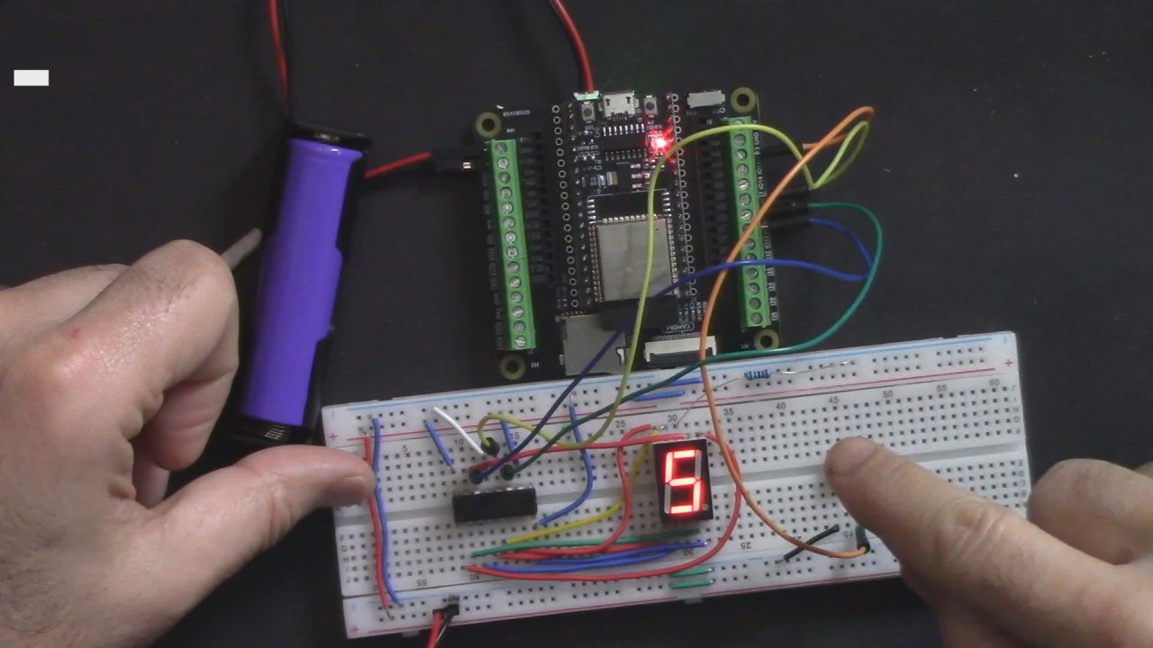
Wiring Instructions
ESP32-33_digital-dice-wiring
To wire the digital dice, start by setting up the power connections. Connect the ground (blue line) on your breadboard to the ground pin on the ESP32 and ensure that all ground points are interconnected. Next, connect a 3.3V pin from the ESP32 to the power rail (red line) on the breadboard.
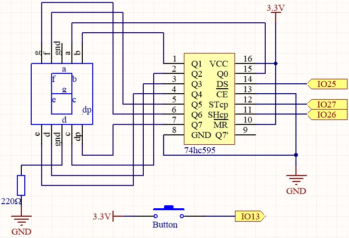
ESP32-33_digital-dice-schematic
For the 74HC595 shift register, ensure that pin 1 is connected to the 3.3V rail, and pin 8 to ground. Connect the data output pin (DS) to pin 25 on the ESP32, the shift clock pin (SHCP) to pin 26, and the storage clock pin (STCP) to pin 27. The push button should be connected between pin 13 on the ESP32 and ground, allowing it to pull the pin low when pressed.
Code Examples & Walkthrough
In the code, we first define the pins used for the shift register and the button. The button pin is defined as buttonPin and is set to pin 13 on the ESP32. The data array datArray contains the binary representations of the numbers 0-9 for the seven-segment display.
const int STcp = 27;//ST_CP
const int SHcp = 26;//SH_CP
const int DS = 25; //DS
const int buttonPin = 13;
int datArray[] = {0x3f,0x06,0x5b,0x4f,0x66,0x6d,0x7d,0x07,0x7f,0x6f};
In the setup() function, we set the button pin to input mode and the shift register pins to output mode. This prepares the pins for reading input from the button and for sending data to the display.
The main logic of the program is found in the loop() function. It checks if the button is pressed, generates a random number, and calls the show_number() function to display the number on the seven-segment display.
The show_number() function sends the appropriate value from the data array to the shift register, which then controls the segments of the display to show the generated number. This function is crucial for visual feedback when the button is pressed.
74HC595 LED Display: Seven Segment explained
Demonstration / What to Expect
When the setup is complete and the code is uploaded, pressing the button will generate a random number between 1 and 6, which will be displayed on the seven-segment display. If everything is wired correctly, the display should show a number each time the button is pressed. Be cautious of floating inputs; ensure that the button is properly connected to ground to avoid erratic behavior (in video at 1:30).
Video Timestamps
00:00 Start
1:48 Project introduction
3:40 Wiring for Digital Dice Explained
13:16 Arduino Code for Digital Dice explained
19:19 Selecting ESP32 Board and COM port in Arduino IDE