In this tutorial, we will create a project using an ESP32 microcontroller and a WS2812 LED strip that can change its direction based on obstacle detection. When the LED strip is moving forward, it will display random colors, and upon detecting an obstacle, it will switch to a predetermined color and reverse direction. This project showcases the capabilities of the ESP32 in combination with an infrared obstacle avoidance sensor.
ESP32-31-flowing-light-main2
Throughout this tutorial, we will cover the necessary hardware components, wiring instructions, and the code required to bring this project to life. For a more visual explanation, be sure to check the video linked below (in video at 00:00).
Hardware Explained
This project requires several components, including the ESP32 microcontroller, a WS2812 LED strip, and an infrared obstacle avoidance sensor. The ESP32 is a powerful microcontroller that features built-in Wi-Fi and Bluetooth, making it perfect for IoT applications. The WS2812 LED strip is a programmable RGB LED strip that allows for individual control of each LED, enabling us to create dynamic lighting effects.
The infrared obstacle avoidance sensor works by emitting infrared light and detecting reflections from nearby objects. When an obstacle is detected, the sensor changes its output state, allowing the ESP32 to respond accordingly by altering the LED strip's behavior.
Datasheet Details
Manufacturer
WS2812B
Part number
WS2812B
Logic/IO voltage
3.3 V (typ.)
Supply voltage
5 V (typ.)
Output current (per channel)
20 mA (max)
Peak current (per channel)
60 mA (max)
PWM frequency guidance
400 Hz (typ.)
Input logic thresholds
0.3 Vcc (high), 0.1 Vcc (low)
Voltage drop / RDS(on) / saturation
1.2 V (max)
Thermal limits
85 °C (max)
Package
Surface mount
Notes / variants
Available in various lengths and densities
Ensure the LED strip is powered with 5 V for optimal performance.
Use a suitable resistor for the data pin to prevent signal integrity issues.
Be cautious of the output current limitations to avoid overheating.
Properly decouple the power supply to prevent voltage spikes.
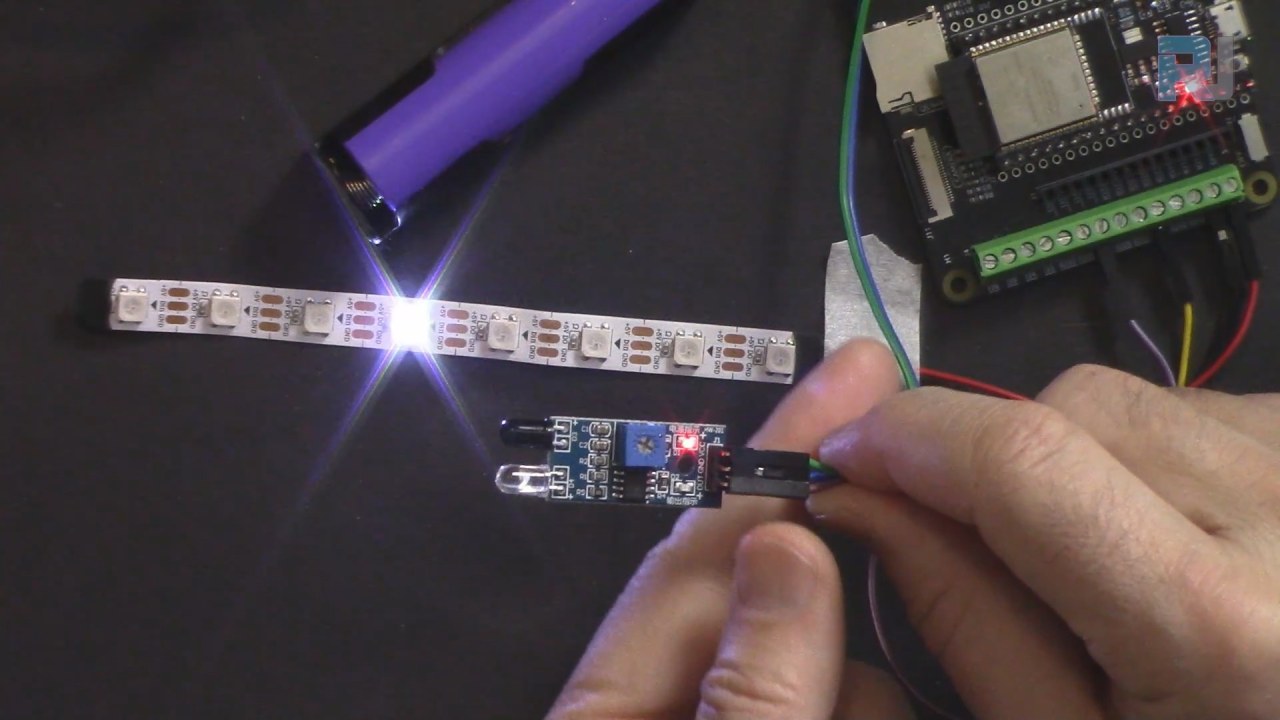
Adjust the infrared sensor carefully to achieve the desired detection range.
Wiring Instructions
ESP32-31-flowing-light-wiring
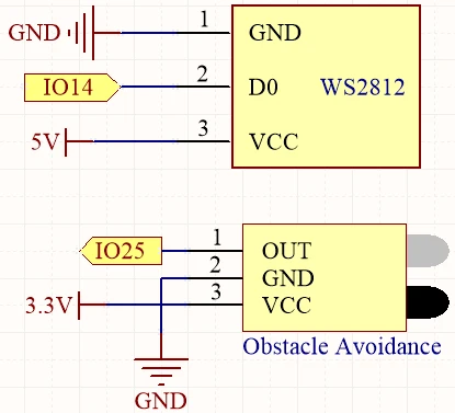
To wire the components, start with the infrared obstacle avoidance sensor. Connect the output pin of the sensor to pin 25 on the ESP32. The middle pin should be connected to ground, and the last pin (VCC) should be connected to a 3.3 V power source.
ESP32-31-flowing-light-schematic
Next, for the WS2812 LED strip, connect the data pin (usually the yellow wire) to pin 14 on the ESP32. The red wire should be connected to a 5 V power source, and the black wire should be connected to ground. Make sure to secure all connections properly to prevent any loose wiring.
Code Examples & Walkthrough
Here is a brief overview of the code that runs this project. First, we define the number of pixels in the LED strip and the data pin used for communication:
#define NUM_PIXELS 8
#define DATA_PIN 14
In the setup() function, we initialize the LED strip and the infrared sensor:
In the loop() function, we check if an obstacle is detected and control the LED strip accordingly:
if (avoid_value) {
    for (int i = 0; i < NUM_PIXELS; i++) {
      pixels.setPixelColor(i, color);
      pixels.show();
      pixels.setPixelColor(i, 0);
      delay(100);
    }
  } else {
    for (int i = NUM_PIXELS - 1; i >= 0; i--) {
      pixels.setPixelColor(i, color);
      pixels.show();
      pixels.setPixelColor(i, 0);
      delay(100);
    }
  }
This code allows the LED strip to display random colors when moving forward and change direction when an obstacle is detected. The full code loads below the article, so be sure to check it out for all the details.
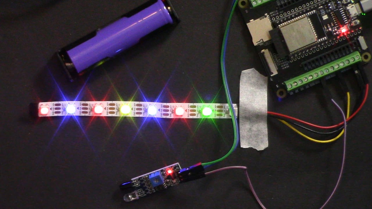
Demonstration / What to Expect
When the setup is complete and the code is uploaded, the LED strip should begin displaying random colors while moving forward. When an obstacle is detected, the strip will switch to a predetermined color (such as green) and reverse direction. If the obstacle is removed, the strip will resume moving forward with random colors. Be aware that the detection range of the infrared sensor may vary based on the power supply used (in video at 10:30).
Video Timestamps
00:00 Start
2:14 Introduction to project
4:58 Wiring explained
7:41 Adjusting Obstacle Avoidance Sensor
10:03 Arduino code explained
15:40 Selecting ESP32 board and COM port in Arduino IDE