ESP32 Tutorial 44/55 - ESP32 Camera Web Server Video Stream Over Wifi CAM-2 | SunFounder's ESP32 kit
In this tutorial, we will create a real-time weather station using the ESP32 and its camera extension. This project will enable the ESP32 to display weather data such as temperature and humidity on an LCD screen, while also streaming video over Wi-Fi. By the end of this tutorial, you will have a fully functional weather station that updates every 10 seconds, providing valuable weather information at your fingertips. For more clarity, refer to the video (in video at 00:00).

Hardware Explained
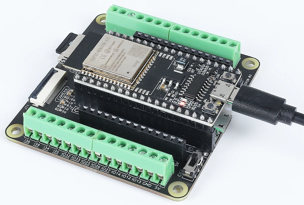
The main components of this project include the ESP32 microcontroller, an LCD display, and a camera module. The ESP32 is a powerful microcontroller that features built-in Wi-Fi and Bluetooth capabilities, allowing it to connect to the internet and communicate with other devices. The camera module enables video streaming, while the LCD display presents weather information to the user.
The LCD used in this project is a 20x4 character display, which can show a significant amount of information at once. It is connected to the ESP32 for displaying the temperature, humidity, and other weather data fetched from an online API. The ESP32 also includes a battery management system, allowing it to operate wirelessly.
Datasheet Details
| Manufacturer | Espressif |
|---|---|
| Part number | ESP32-WROOM-32 |
| Logic/IO voltage | 3.3 V |
| Supply voltage | 3.0 - 3.6 V |
| Output current (per GPIO) | 12 mA |
| Peak current (per GPIO) | 40 mA |
| PWM frequency guidance | 1 kHz |
| Input logic thresholds | 0.3 * VDD to 0.7 * VDD |
| Voltage drop / RDS(on) / saturation | 0.1 V (typ.) |
| Thermal limits | 125 °C |
| Package | QFN48 |
| Notes / variants | Includes PSRAM options |
- Ensure proper power supply (3.0 - 3.6 V).
- Use heat sinks for high current applications.
- Be cautious with GPIO current limits (12 mA per pin).
- Connect the LCD and camera properly to avoid miscommunication.
- Check Wi-Fi credentials and API keys for connectivity issues.
Wiring Instructions
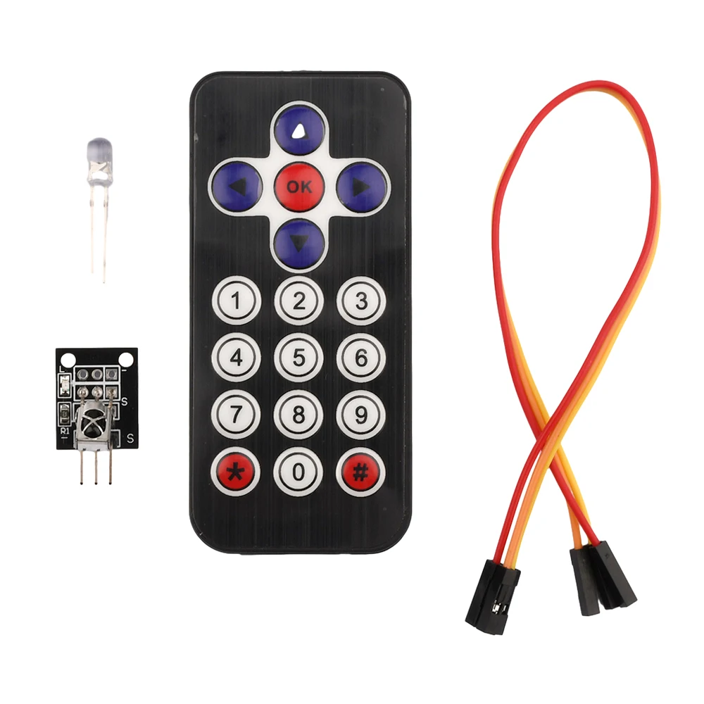
To wire the ESP32 with the LCD and camera module, start by connecting the power and ground pins. Connect the ground pin of the ESP32 to the ground of the LCD and camera. Then, connect the 5V pin of the ESP32 to the VCC of the LCD. For the camera, connect the brown wire to the ground, the red wire to 5V, the yellow wire to GPIO 21, and the orange wire to GPIO 22. Ensure that the connections are secure to avoid any issues during operation.
Next, connect the LCD to the appropriate GPIO pins. The specific pins may vary based on your setup, but typically, you will connect the control pins to designated GPIOs on the ESP32. Make sure to refer to the datasheet or pinout diagram for your specific LCD model to confirm the correct wiring. After completing these connections, double-check all wiring for any loose or incorrect connections.
Code Examples & Walkthrough
In the code, we first include the necessary libraries for handling the camera and Wi-Fi functionalities. The essential identifiers are declared, including ssid and password for Wi-Fi credentials. The configuration for the camera is set up using the camera_config_t structure, where we define various parameters such as pixel format and frame size.
const char* ssid = "SSID";
const char* password = "PASSWORD";

void setup() {
  Serial.begin(115200);
  camera_config_t config;
  // ... (configuration settings)
  esp_err_t err = esp_camera_init(&config);
  // Check for errors
}
This snippet initializes the camera and checks for any errors during setup. If the camera fails to initialize, an error message is printed to the serial monitor.
Next, we handle the Wi-Fi connection and start the camera server. The connection loop continues until a successful Wi-Fi connection is established, which is crucial for fetching weather data from the API.
WiFi.begin(ssid, password);
while (WiFi.status() != WL_CONNECTED) {
  delay(500);
  Serial.print(".");
}
startCameraServer();
In this section, we initiate the Wi-Fi connection and print dots to the serial monitor until the connection is established. Once connected, the camera server is started, allowing video streaming.
The complete code will load below the article, where you can see how all parts come together.
Demonstration / What to Expect
Once everything is wired and the code is uploaded, you can expect the ESP32 to connect to the Wi-Fi network and start fetching weather data every 10 seconds. The temperature and humidity readings will be displayed on the LCD screen. Additionally, the camera will stream video over Wi-Fi, which can be accessed via the local IP address printed in the serial monitor. If the Wi-Fi connection fails, the ESP32 will notify you through the serial output (in video at 10:00).
Video Timestamps
- 00:00 Start
- 1:42 Introduction to the ESP32-Cam
- 4:30 Arduino code explained
- 7:35 Selecting ESP32 Board and COM port in Arduino IDE
- 9:17 Demonstration
- 12:06 Demonstration on Mobile Phone
图像
#include "esp_camera.h"
#include <WiFi.h>

//
// WARNING!!! PSRAM IC required for UXGA resolution and high JPEG quality
//            Ensure ESP32 Wrover Module or other board with PSRAM is selected
//            Partial images will be transmitted if image exceeds buffer size
//
//            You must select partition scheme from the board menu that has at least 3MB APP space.
//            Face Recognition is DISABLED for ESP32 and ESP32-S2, because it takes up from 15
//            seconds to process single frame. Face Detection is ENABLED if PSRAM is enabled as well

// ===================
// Select camera model
// ===================
//#define CAMERA_MODEL_WROVER_KIT // Has PSRAM
// #define CAMERA_MODEL_ESP_EYE // Has PSRAM
//#define CAMERA_MODEL_ESP32S3_EYE // Has PSRAM
//#define CAMERA_MODEL_M5STACK_PSRAM // Has PSRAM
//#define CAMERA_MODEL_M5STACK_V2_PSRAM // M5Camera version B Has PSRAM
//#define CAMERA_MODEL_M5STACK_WIDE // Has PSRAM
//#define CAMERA_MODEL_M5STACK_ESP32CAM // No PSRAM
//#define CAMERA_MODEL_M5STACK_UNITCAM // No PSRAM
#define CAMERA_MODEL_AI_THINKER // Has PSRAM
//#define CAMERA_MODEL_TTGO_T_JOURNAL // No PSRAM
//#define CAMERA_MODEL_XIAO_ESP32S3 // Has PSRAM
// ** Espressif Internal Boards **
//#define CAMERA_MODEL_ESP32_CAM_BOARD
//#define CAMERA_MODEL_ESP32S2_CAM_BOARD
//#define CAMERA_MODEL_ESP32S3_CAM_LCD

#include "camera_pins.h"

// Replace the next variables with your SSID/Password combination
const char* ssid = "SSID";
const char* password = "PASSWORD";

void startCameraServer();
void setupLedFlash(int pin);

void setup() {
  Serial.begin(115200);
  Serial.setDebugOutput(true);
  Serial.println();

  camera_config_t config;
  config.ledc_channel = LEDC_CHANNEL_0;
  config.ledc_timer = LEDC_TIMER_0;
  config.pin_d0 = Y2_GPIO_NUM;
  config.pin_d1 = Y3_GPIO_NUM;
  config.pin_d2 = Y4_GPIO_NUM;
  config.pin_d3 = Y5_GPIO_NUM;
  config.pin_d4 = Y6_GPIO_NUM;
  config.pin_d5 = Y7_GPIO_NUM;
  config.pin_d6 = Y8_GPIO_NUM;
  config.pin_d7 = Y9_GPIO_NUM;
  config.pin_xclk = XCLK_GPIO_NUM;
  config.pin_pclk = PCLK_GPIO_NUM;
  config.pin_vsync = VSYNC_GPIO_NUM;
  config.pin_href = HREF_GPIO_NUM;
  config.pin_sccb_sda = SIOD_GPIO_NUM;
  config.pin_sccb_scl = SIOC_GPIO_NUM;
  config.pin_pwdn = PWDN_GPIO_NUM;
  config.pin_reset = RESET_GPIO_NUM;
  config.xclk_freq_hz = 20000000;
  config.frame_size = FRAMESIZE_UXGA;
  config.pixel_format = PIXFORMAT_JPEG; // for streaming
  // config.pixel_format = PIXFORMAT_RGB565; // for face detection/recognition
  config.grab_mode = CAMERA_GRAB_WHEN_EMPTY;
  config.fb_location = CAMERA_FB_IN_PSRAM;
  config.jpeg_quality = 12;
  config.fb_count = 1;

  // if PSRAM IC present, init with UXGA resolution and higher JPEG quality
  //                      for larger pre-allocated frame buffer.
  if(config.pixel_format == PIXFORMAT_JPEG){
    if(psramFound()){
      config.jpeg_quality = 10;
      config.fb_count = 2;
      config.grab_mode = CAMERA_GRAB_LATEST;
    } else {
      // Limit the frame size when PSRAM is not available
      config.frame_size = FRAMESIZE_SVGA;
      config.fb_location = CAMERA_FB_IN_DRAM;
    }
  } else {
    // Best option for face detection/recognition
    config.frame_size = FRAMESIZE_240X240;
#if CONFIG_IDF_TARGET_ESP32S3
    config.fb_count = 2;
#endif
  }

#if defined(CAMERA_MODEL_ESP_EYE)
  pinMode(13, INPUT_PULLUP);
  pinMode(14, INPUT_PULLUP);
#endif

  // camera init
  esp_err_t err = esp_camera_init(&config);
  if (err != ESP_OK) {
    Serial.printf("Camera init failed with error 0x%x", err);
    return;
  }

  sensor_t * s = esp_camera_sensor_get();
  // initial sensors are flipped vertically and colors are a bit saturated
  if (s->id.PID == OV3660_PID) {
    s->set_vflip(s, 1); // flip it back
    s->set_brightness(s, 1); // up the brightness just a bit
    s->set_saturation(s, -2); // lower the saturation
  }
  // drop down frame size for higher initial frame rate
  if(config.pixel_format == PIXFORMAT_JPEG){
    s->set_framesize(s, FRAMESIZE_QVGA);
  }

#if defined(CAMERA_MODEL_M5STACK_WIDE) || defined(CAMERA_MODEL_M5STACK_ESP32CAM)
  s->set_vflip(s, 1);
  s->set_hmirror(s, 1);
#endif

#if defined(CAMERA_MODEL_ESP32S3_EYE)
  s->set_vflip(s, 1);
#endif

// Setup LED FLash if LED pin is defined in camera_pins.h
#if defined(LED_GPIO_NUM)
  setupLedFlash(LED_GPIO_NUM);
#endif

  WiFi.begin(ssid, password);
  WiFi.setSleep(false);

  while (WiFi.status() != WL_CONNECTED) {
    delay(500);
    Serial.print(".");
  }
  Serial.println("");
  Serial.println("WiFi connected");

  startCameraServer();

  Serial.print("Camera Ready! Use 'http://");
  Serial.print(WiFi.localIP());
  Serial.println("' to connect");
}

void loop() {
  // Do nothing. Everything is done in another task by the web server
  delay(10000);
}
Common Course Links
Common Course Files
资源与参考
-
文档ESP32教程 44/55 - SunFounder相机网络服务器文档页面docs.sunfounder.com
文件📁
没有可用的文件。