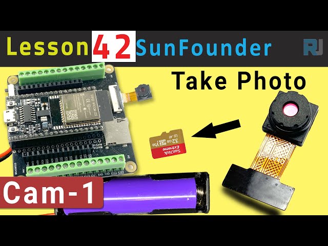
ESP32 Tutorial 42/55 - Taking Photo with Camera save on Micro SD CAM-1 | SunFounder's ESP32 kit
In this tutorial, we will be using the ESP32 microcontroller along with its extension board from SunFounder to capture photos using a camera and save them directly onto a micro SD card. This project utilizes the built-in capabilities of the ESP32, including Wi-Fi and Bluetooth, to create a compact photo-taking device. By the end of this tutorial, you'll have a working setup that can take and store images, which can then be accessed later on a computer.

For those who are new to the ESP32 ecosystem, this kit provides a versatile platform for various projects, including this one. The camera used in this project is the OV2640, which offers a resolution of 1600x1200 pixels. While it may not match the quality of modern smartphones, it is sufficient for basic image capturing tasks. To clarify any steps, be sure to check the video accompanying this tutorial (in video at 00:00).

Hardware Explained
The main components in this project include the ESP32 microcontroller, the camera module (OV2640), and a micro SD card for storage. The ESP32 is a powerful microcontroller with integrated Wi-Fi and Bluetooth capabilities, making it ideal for IoT applications. The camera module captures images, which are then processed by the ESP32.
The micro SD card acts as a storage medium for the captured images. In this setup, the ESP32 communicates with the camera module using specific GPIO pins, and the images are saved in JPEG format on the SD card. This allows for easy retrieval and viewing of photos later.
- Ensure the camera is correctly oriented when inserting into the ESP32 board.
- Use a micro SD card with a capacity of 32 GB or less to avoid compatibility issues.
- Connect GPIO 0 to GND for programming mode.
- Pay attention to the power supply to avoid brownout problems.
- Keep the camera steady while taking photos to avoid blurry images.
Wiring Instructions
To wire the ESP32 camera module, first ensure the ESP32 is powered off. Connect the micro SD card module to the ESP32 using the following pins: connect the CS pin of the SD card to the ESP32's GPIO 5, MOSI to GPIO 23, MISO to GPIO 19, and SCK to GPIO 18. Next, connect the camera module pins as follows: PWDN to GPIO 32, XCLK to GPIO 0, SIOD to GPIO 26, and SIOC to GPIO 27. The pixel data pins Y2 to Y9 should be connected to GPIO 5 through GPIO 39 as defined in your code.
Make sure to connect the ground and power pins appropriately. The ESP32 can be powered by the battery included in the kit. After wiring, ensure the connections are secure before powering on the device. If you follow the instructions closely, you should see the camera initialize correctly when you upload the code.
Code Examples & Walkthrough


In the code, we start by including necessary libraries and defining camera pin configurations. The variable pictureNumber is initialized to keep track of the number of photos taken.
int pictureNumber = 0;

void setup() {
  WRITE_PERI_REG(RTC_CNTL_BROWN_OUT_REG, 0);  // Disable brownout detector
  Serial.begin(115200);
  camera_config_t config;
  // Configuration settings for the camera
  config.ledc_channel = LEDC_CHANNEL_0;
  // Additional camera settings...
}
The setup function initializes the serial communication and configures the camera settings. The configuration includes parameters like ledc_channel, pin_d0, and xclk_freq_hz for optimal performance.
Next, we handle the image capturing process by using a loop to take multiple pictures. The image data is saved to the SD card with a filename based on the pictureNumber.
for (int shoot = 0; shoot < 5; shoot++) {
    camera_fb_t *fb = esp_camera_fb_get(); // Take Picture
    String path = "/picture" + String(pictureNumber) + ".jpg"; // File path
    File file = fs.open(path.c_str(), FILE_WRITE); // Open file to write
    // Write image data to file
    file.write(fb->buf, fb->len);
    // Update picture number in EEPROM
    EEPROM.write(0, pictureNumber);
}
This loop captures up to five images, where each image is saved with a unique filename. The use of EEPROM allows the program to remember the last picture number, ensuring that each new image has a unique identifier.
Demonstration / What to Expect
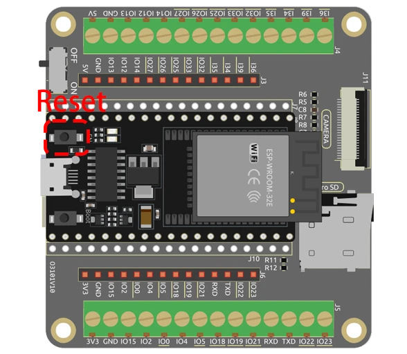
When you run the code, the ESP32 will initialize the camera and the SD card. After pressing the reset button on the ESP32, it will take a series of pictures, which will be numbered sequentially from 0 to 255 based on the EEPROM value. After capturing the images, you can remove the micro SD card and view the pictures on your computer.
Common pitfalls include ensuring the micro SD card is properly formatted and inserted, as well as maintaining a stable camera position to avoid blurry images. If you encounter issues with the camera not capturing images, double-check the wiring and configurations set in the code (in video at 06:45).
Video Timestamps
- 00:00 Start
- 1:39 Introduction
- 5:19 ESP32 Camera Code explained
- 11:10 Selecting ESP32 board and COM port in Arduino IDE
- 12:52 Taking photos indoor and outdoor test
图像
This code has not been parsed yet. Please return to the admin panel to parse it.Common Course Links
Common Course Files
资源与参考
-
文档ESP32教程 42/55 - SunFounder文档页面拍照docs.sunfounder.com
文件📁
没有可用的文件。