In this tutorial, we will create a remote temperature monitoring system using the ESP32 and the MQTT protocol. This project allows us to publish temperature data to an MQTT broker and control an LED remotely using a web interface. By pressing a button, we can send temperature readings to the cloud, and we can also receive commands to turn the LED on or off.
esp32-47-mqt-1
The ESP32 is a powerful microcontroller that features built-in Wi-Fi and Bluetooth, making it ideal for Internet of Things (IoT) applications. In this setup, we will use an NTC thermistor to measure temperature, a push button to trigger the readings, and an LED to indicate status. The data will be sent to HiveMQ, a popular MQTT broker, where it can be accessed remotely (in video at 00:45).
esp32-47-mqt-2
Hardware Explained
For this project, we will utilize the following components:
ESP32 Microcontroller: This board serves as the central processing unit, handling Wi-Fi connections and MQTT communications.
NTC Thermistor: This temperature sensor changes its resistance based on temperature. It provides an analog signal that the ESP32 can read to determine the current temperature.
LED: This light-emitting diode will be used to indicate the status based on commands received via MQTT.
Push Button: This button will trigger the ESP32 to read the temperature and publish it to the MQTT broker.
Datasheet Details
Manufacturer
SunFounder
Part number
ESP32
Logic/IO voltage
3.3 V
Supply voltage
5 V (via USB)
Output current (per channel)
12 mA max
PWM frequency guidance
Up to 40 kHz
Input logic thresholds
0.3 V (low), 2.4 V (high)
Thermal limits
-40 to 85 °C
Package
ESP32-WROOM-32
Ensure proper voltage levels to avoid damage.
Use pull-up resistors for the push button to ensure stable readings.
Decoupling capacitors can help stabilize the power supply.
Be cautious with the thermistor's wiring to avoid incorrect readings.
Verify your MQTT broker details for successful connection.
Wiring Instructions
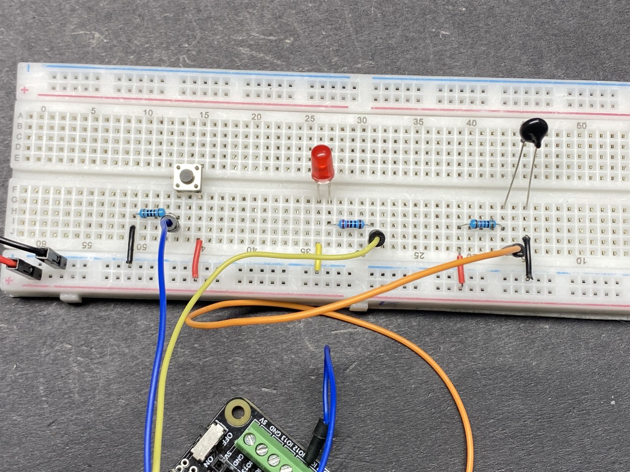
esp32-47-mqtt-wiring
To wire the components, start by connecting the NTC thermistor. Connect one pin of the thermistor to the 3.3 V supply on the ESP32. The other pin connects to pin 36 on the ESP32, and it should also connect to a 10 kΩ resistor, which is then connected to ground. This creates a voltage divider that allows the ESP32 to read the thermistor's resistance.
Next, connect the LED. The longer pin (anode) of the LED connects to pin 4 on the ESP32 through a 220 Ω resistor, while the shorter pin (cathode) connects to ground. For the push button, connect one side to 3.3 V and the other side to pin 14 on the ESP32. Additionally, connect a 10 kΩ resistor from the button pin to ground to ensure a stable LOW state when the button is not pressed.
Install Required library
The PubSubClient library is used here, you can install it from the Library Manager.
esp32-47-mqtt-library
Code Examples & Walkthrough
In the setup, we initialize the serial communication, set up the Wi-Fi connection, and configure the MQTT server. Here's a snippet of the setup code:
This part of the code establishes the connection to the Wi-Fi network and sets up the MQTT server. The pin modes for the button and LED are also configured here.
The loop function continuously checks the button state and publishes temperature data when pressed. Here's a focused excerpt from the loop:
void loop() {
  if (!client.connected()) {
    reconnect();
  }
  client.loop();
  if (digitalRead(buttonPin)) {
    long now = millis();
    if (now - lastMsg > 5000) {
      lastMsg = now;
      char tempString[8];
      dtostrf(thermistor(), 1, 2, tempString);
      client.publish("SF/TEMP", tempString);
    }
  }
}
In this loop, we check if the ESP32 is connected to the MQTT broker. If the button is pressed, it reads the temperature from the thermistor and publishes it to the topic "SF/TEMP" every 5 seconds.
Demonstration / What to Expect
When the project is set up and running, pressing the button will publish the current temperature to the MQTT broker. You can monitor this data from any MQTT client. Additionally, you can send messages to control the LED; sending "on" will light it up, while "off" will turn it off. Watch for the expected behavior in the video at 15:30, where the temperature readings are shown after each button press.
Video Timestamps
00:00 Start
2:05 Introduction to the project
7:06 Free HiveMQ service
7:56 Wiring explained
11:11 Arduino code explained
18:46 Selecting ESP32 board and COM port in Arduino IDE