ESP32 Tutorial 55/55 - How to measure 12V, 24V or 100V DC voltage | SunFounder's ESP32 IoT Learning kit
In this tutorial, we will learn how to use the ESP32 to measure various DC voltages, including 12V, 24V, and even up to 100V. By utilizing a voltage divider circuit made from two resistors, we can safely measure higher voltages without risking damage to the ESP32 microcontroller. This project will demonstrate how to read these voltages and display them on the serial monitor, providing valuable insights into your power sources.

Watch the video for a comprehensive explanation (in video at 00:00). We will be using a simple voltage divider configuration to achieve this, ensuring that we can measure voltages that exceed the ESP32's maximum input levels safely. This tutorial is perfect for those looking to expand their knowledge of the ESP32 and its capabilities.
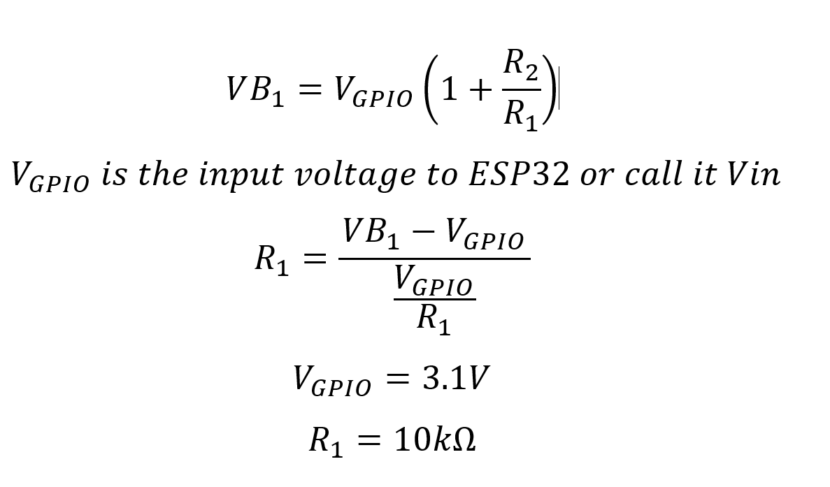
Formula to calculate voltage
Hardware Explained
The key components for this project include the ESP32 microcontroller, two resistors forming a voltage divider, and the power source you wish to measure. The ESP32 is equipped with built-in Wi-Fi and Bluetooth capabilities, making it a versatile choice for IoT projects. The voltage divider, made up of two resistors, allows us to scale down the voltage to a safe level that the ESP32 can process.
In this setup, one resistor, R1, is fixed at 10kΩ, while the second resistor, R2, can vary depending on the maximum voltage you wish to measure. The voltage across R1 is what we will read using the ESP32's analog input pin, allowing us to calculate the original voltage from the power source.
- Ensure resistors are 1% tolerance for accurate measurements.
- Use a voltage divider to prevent exceeding ESP32's input voltage ratings.
- Keep
R1at 10kΩ and adjustR2based on the voltage range. - Check connections to avoid floating inputs that can lead to inaccurate readings.
- Use a stable power source for consistent voltage measurements.
Wiring Instructions
To wire the circuit, start by connecting one end of the R1 resistor (10kΩ) to your voltage source, and the other end to the ESP32's GPIO pin 35. This pin will read the voltage across R1. Next, connect the R2 resistor (which can be 100kΩ or another value depending on your needs) between the junction point of R1 and the ground. Make sure that the ground of the power source is also connected to the ESP32's ground.
For example, if measuring 24V, connect the power supply's positive terminal to R1, then connect the other end of R1 to pin 35 and the junction of the two resistors. The free end of R2 should go to ground. This configuration will allow the ESP32 to read a scaled-down voltage safely.
Code Examples & Walkthrough
const int R1 = 10000; // Resistor 1 value
const int R2 = 100000; // Resistor 2 value
const int VinPin = 35; // Voltage input pin
In this excerpt, we define the values for our resistors, R1 and R2, as well as the analog pin VinPin that we will use to read the voltage. These constants are crucial for our voltage calculations.
void readVoltage() {
  uint32_t voltage_mV = analogReadMilliVolts(VinPin); // Read in millivolts
  VB1 = (((float) voltage_mV) / 1000.0) * (1 + (float)R2/(float)R1);
}
This function reads the voltage in millivolts from the specified pin and calculates the actual voltage VB1 using the voltage divider formula. This is important for translating the scaled-down voltage back to the original value.
void maxVoltage() {
  float maxVoltage = (3.1) * (1 + (float)R2/(float)R1);
}
Here, we define a function to calculate and print the maximum voltage that can be safely measured based on the resistor values. This function is critical for ensuring we do not exceed the ESP32's voltage limits.
Demonstration / What to Expect
When you run the code, you should see the measured voltage displayed on the serial monitor. As you adjust the input voltage, the readings should reflect these changes in real-time, demonstrating the ESP32's ability to measure various DC voltages accurately. If you experience fluctuations in the readings, consider averaging multiple samples to achieve a more stable result (in video at 12:30).
Video Timestamps
- 00:00 Start
- 1:59 Introduction to the project
- 5:45 Voltage divider
- 7:33 Wiring explained
- 9:14 Arduino Code explained
- 14:45 Selecting ESP32 board and COM Port on Arduino IDE
- 16:27 Measuring 30V using ESP32 Demonstration
- 21:36 Changed the R2 to 330k ohm
- 22:33 Minimum voltage measurement
图像
/*
 * 用于测量任何直流电压的ESP32的Arduino代码
 * 作者:Ahmad Shamshiri
 * 观看完整视频解释 https://youtu.be/znBiVlgV9JI
 * www.robojax.com
 * 2024年2月19日
 */
bool debug = false;
const int R1 = 10000; // 我们读取这个电阻两端的电压 ()
const int R2 = 100000;

const int VinPin = 35; // 连接到GPIO14的电位器


 // PWM设置
const int freq = 5000; // PWM频率
const int resolution = 12; // PWM 分辨率(位)
const int channel = 0; // PWM 通道

float VB1;
int mV;

void setup() {
  Serial.begin(115200);
 // 配置PWM
  ledcSetup(channel, freq, resolution);
 // calculatResistor(R1, 24);//10000 欧姆 和 35.0V

}


void loop() {
   readVoltage();

  Serial.print("VB1 Voltage: ");
  Serial.print(VB1); // 将毫伏转换为伏特
  Serial.println("V ");


  delay(500);
}

void readVoltage()
{
  uint32_t voltage_mV = analogReadMilliVolts(VinPin); // 以毫伏为单位读取电压
  if(debug)
  {
    maxVoltage();
    Serial.print("PinVoltage: ");
    Serial.print(voltage_mV);
    Serial.println("mV");
    Serial.println(); // 这添加了一行新内容。
  }
  mV = voltage_mV;
  VB1 = (((float) voltage_mV) / 1000.0)  * (1 + (float)R2/(float)R1);
}

/*
 * 打印最大电压
 */
void maxVoltage()
{
  float maxVoltage = ( 3.1)  * (1 + (float)R2/(float)R1);
    Serial.print("****Maximum Voltage: ");
    Serial.print(maxVoltage);
    Serial.println("V");

} // 最大电压() 结束

void calculatResistor(int r1, float voltage)
{
    Serial.print("Calculating R2 when R1 is :");
    Serial.print(r1);
    Serial.print(" Ohms and Maximum Input Voltage is ");
    Serial.print(voltage);
    Serial.println("V");
    Serial.print("***** R2 Should Be ");
    float r2 = (voltage - 3.1)/ (3.1/ (float)r1);
    Serial.print(r2 / 1000.0);
    Serial.println(" kilo Ohms");
    while(1);
}
Common Course Links
Common Course Files
资源与参考
尚无可用资源。
文件📁
没有可用的文件。