ESP32 Tutorial 48/55 - Remote Temperature Monitoring and LED control MQTT | SunFounder's ESP32 IoT kit
In this tutorial, we will explore how to utilize the ESP32 module in conjunction with SunFounder's ESP32 extension board to monitor temperature and humidity remotely using the Adafruit IO platform. Additionally, we'll implement the functionality to control an LED via a web interface. By the end of this project, you'll be able to view real-time temperature and humidity data and toggle an LED on and off from your browser.
This project leverages the MQTT protocol for efficient communication between the ESP32 and the Adafruit IO service. MQTT is lightweight and well-suited for IoT applications, allowing us to easily publish sensor data and subscribe to commands for the LED control. For further clarification of the code and wiring, be sure to check the video accompanying this tutorial (in video at 00:00).
Hardware Explained
The main components for this project include the ESP32 microcontroller, a DHT11 temperature and humidity sensor, and an LED. The ESP32 is a powerful microcontroller that features built-in Wi-Fi and Bluetooth capabilities, making it an ideal choice for IoT projects. It can handle multiple tasks and connect to the internet seamlessly.
The DHT11 sensor is responsible for measuring temperature and humidity. It outputs digital signals that can be read by the ESP32. The LED serves as an indicator and can be controlled remotely to demonstrate the effectiveness of the MQTT protocol in managing devices over the internet.
Datasheet Details
| Manufacturer | Adafruit |
|---|---|
| Part number | DHT11 |
| Logic/IO voltage | 3.3 V |
| Supply voltage | 3.3 V |
| Output current (per channel) | 20 mA |
| Peak current (per channel) | 50 mA |
| PWM frequency guidance | N/A |
| Input logic thresholds | 0.3 V (low), 0.7 V (high) |
| Voltage drop / RDS(on) / saturation | N/A |
| Thermal limits | 0 to 50 °C |
| Package | 3-pin |
| Notes / variants | Use DHT22 for higher accuracy. |
- Ensure correct wiring to prevent damage.
- Use a 220 Ohm resistor with the LED for current limiting.
- Use pull-up resistors for the DHT11 data pin if necessary.
- Check Wi-Fi credentials for case sensitivity.
- Monitor serial output for debugging connection issues.
- Keep MQTT topics unique to avoid conflicts.
- Test sensor readings to ensure they are valid.
- Be cautious of the DHT11's response time; it may take time to stabilize readings.
LED = control LED; temperature = publish temperature data; humidity = publish humidity data.
Wiring Instructions
To wire the components, start by connecting the DHT11 sensor. Connect the left pin of the DHT11 to the 3.3V power rail on the breadboard using a red wire. The middle pin of the DHT11 should be connected to pin 13 on the ESP32 using a yellow wire. Finally, connect the right pin of the DHT11 to the ground rail using a blue wire.
Next, for the LED, connect the anode (longer leg) to pin 15 of the ESP32 through a 220 Ohm resistor. Connect the cathode (shorter leg) directly to the ground rail on the breadboard. Make sure all connections are secure and double-check for any loose wires.
Setting up the Dashboard
-
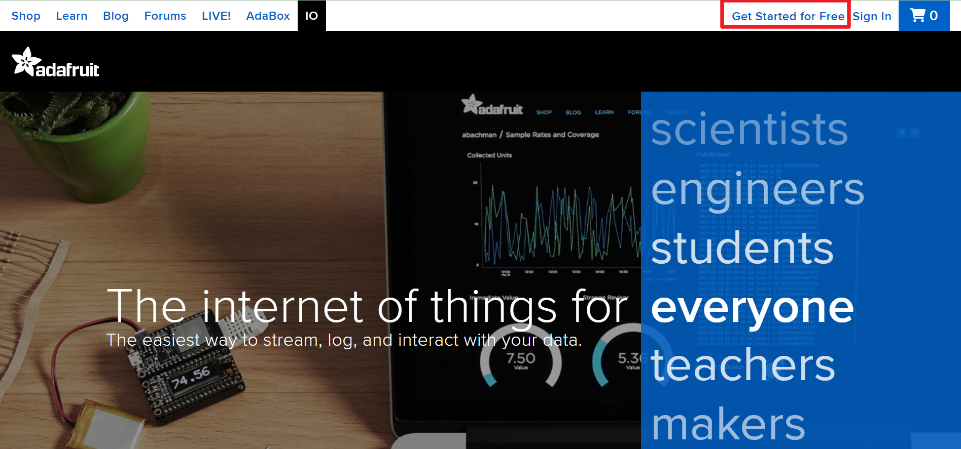
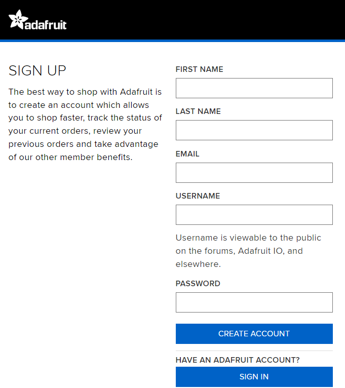
Visit Adafruit IO, then click on Start for free to create a free account.
-
Fill out the form to create an account.
-
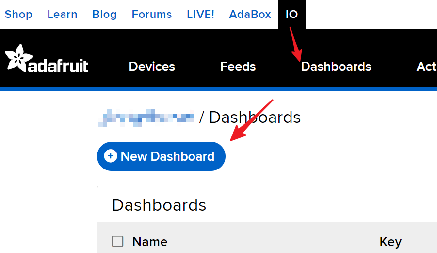
After creating an Adafruit account, you’ll need to reopen Adafruit io. Click on the Dashboards, then click on New Dashboard.
-
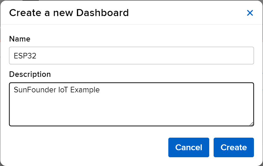
Create a New Dashboard.
-
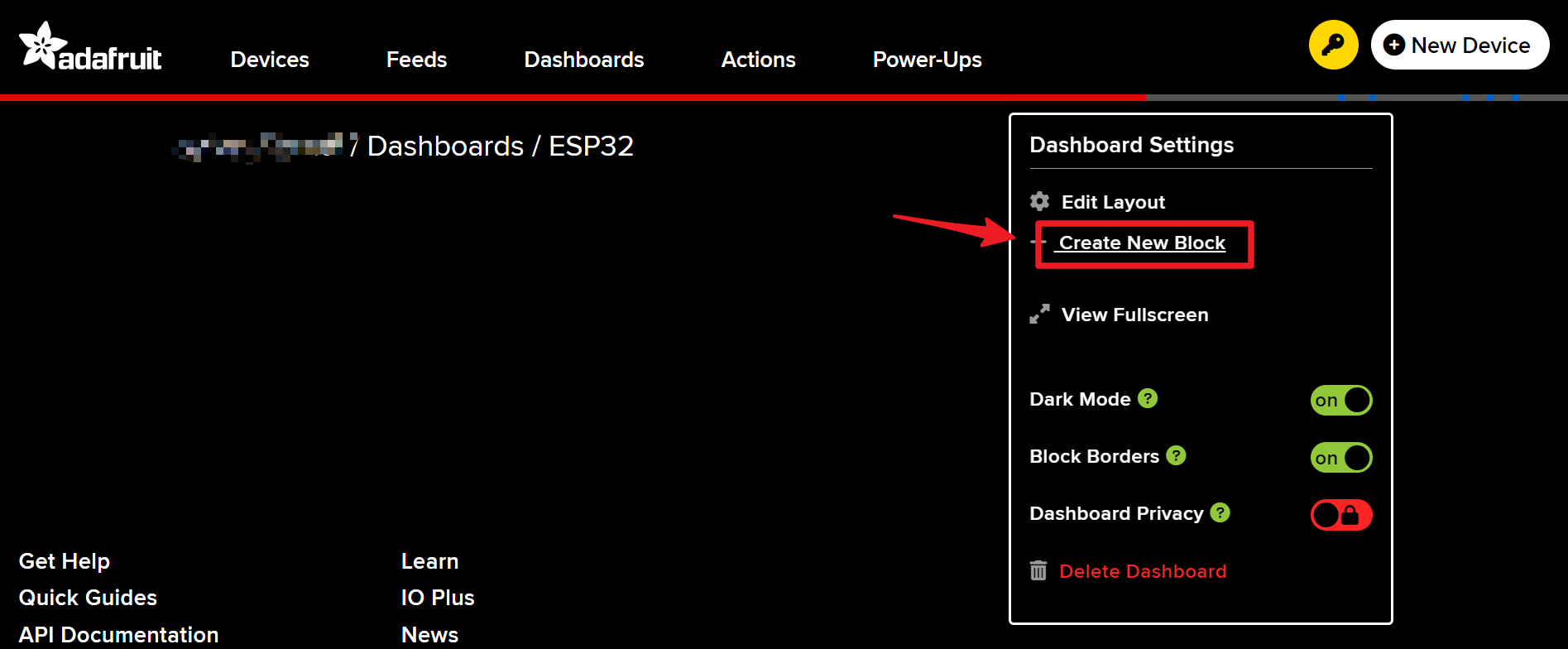
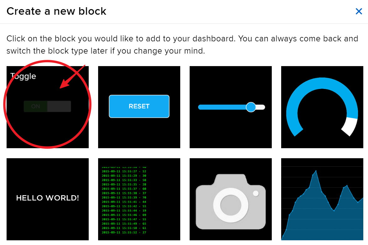
Enter the newly created Dashboard and create a new block.
-
Create 1 Toggle block.
-
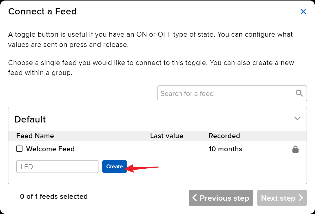
Next, you’ll need to create a new feed here. This toggle will be used to control the LED, and we’ll name this feed “LED”.
-
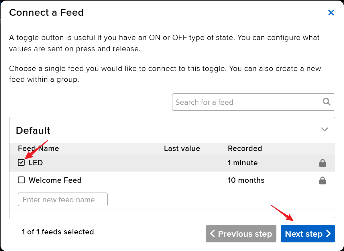
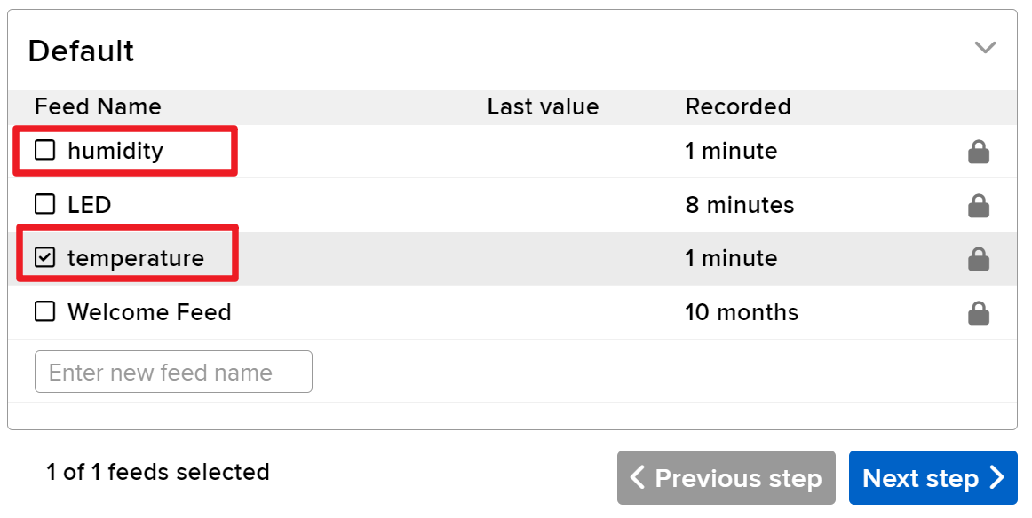
Check the LED feed, then move to the next step.
-
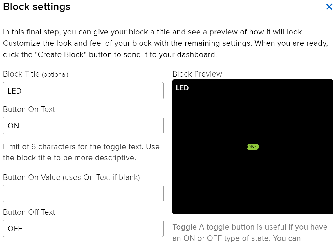
Complete the block settings (mainly Block Title, On Text, and Off Text), then click on the Create block button at the bottom right to finish.
-
We also need to create two Text Blocks next. They will be used to display temperature and humidity. So, create two feeds named temperature and humidity.
-
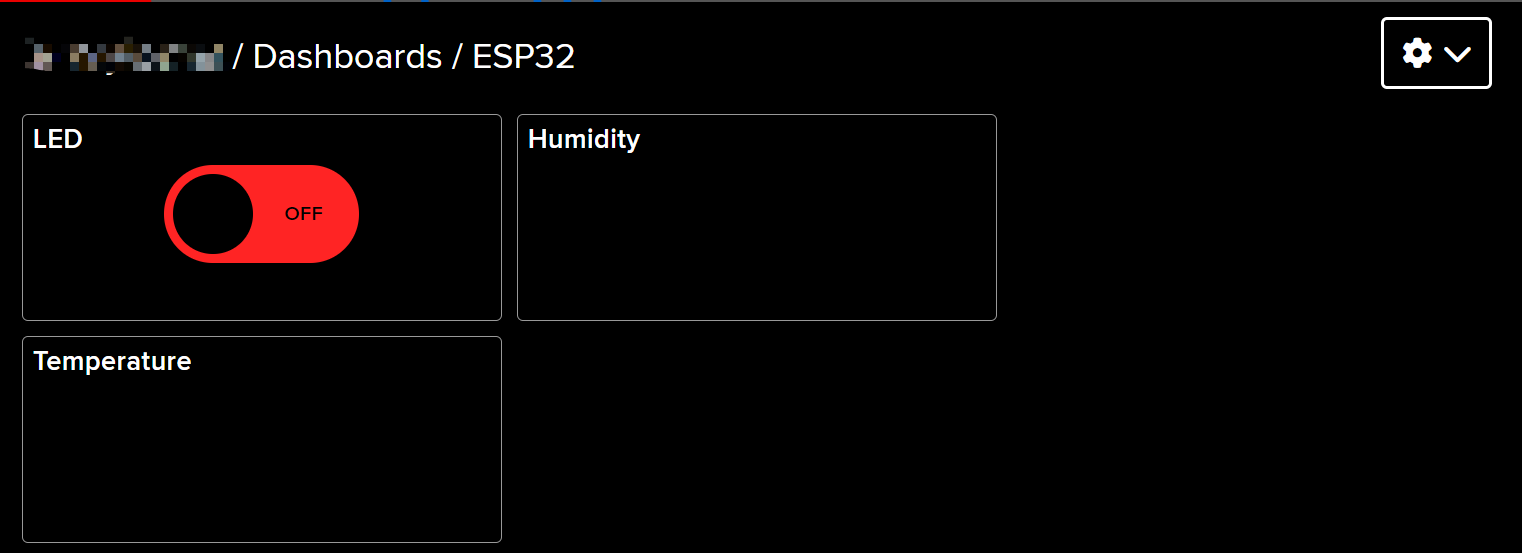
After creation, your Dashboard should look something like this:
-
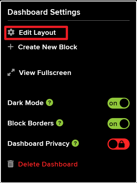
You can adjust the layout by using the Edit Layout option on the Dashboard.
-
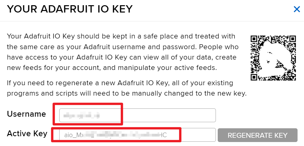
Click on API KEY, and you will see your username and API KEY displayed. Note these down as you’ll need them for your code.
Code Examples & Walkthrough
The code begins by including the necessary libraries, setting up the Wi-Fi credentials, and defining the MQTT parameters. Key identifiers such as AIO_USERNAME and AIO_KEY are used to authenticate with the Adafruit IO service.
#define AIO_USERNAME "YourUsername"
#define AIO_KEY "YourKey"
These lines define your Adafruit IO username and key, which are essential for connecting to the MQTT broker. Ensure these values are accurate to establish a successful connection.
In the setup() function, the Wi-Fi connection is initialized, and the MQTT client is set up with the root CA certificate for secure communication.
WiFi.begin(WLAN_SSID, WLAN_PASS);
client.setCACert(adafruitio_root_ca);
This code connects the ESP32 to the specified Wi-Fi network and sets the root CA for secure MQTT connections. Properly handling these connections is critical for reliable data transmission.
Finally, the loop() function manages the MQTT connection and publishes temperature and humidity readings at regular intervals.
mqtt.processPackets(5000);This line allows the ESP32 to process incoming messages for subscribed topics, ensuring that the device remains responsive to commands sent from the web interface.
For the complete code, please refer to the full program loaded below the article.
Demonstration / What to Expect
Upon successful setup, you should see real-time updates of temperature and humidity on your Adafruit IO dashboard. You can also toggle the LED on and off through the web interface. If the LED does not respond as expected, check your wiring and ensure that the MQTT topic names match those defined in the code.
Be aware that certain MQTT connection errors may occur due to expired certificates. Ensure you have the latest root CA certificate in your code to avoid these issues (in video at 15:30).
Video Timestamps
- 00:00 Start
- 1:50 Introduction to project
- 3:16 What is MQTT
- 6:36 Adafruit IO setup
- 11:13 wiring
- 13:38 Arduino code explained
- 22:03 Selecting ESP32 board and COM port
- 23:44 Project demonstration
- 27:05 Updating dashboard
This code has not been parsed yet. Please return to the admin panel to parse it.This code has not been parsed yet. Please return to the admin panel to parse it.Common Course Links
Common Course Files
资源与参考
-
文档ESP32 教程 48/55 - SunFounder 文档页面:使用 Adafruit IO 进行温湿度监控docs.sunfounder.com
文件📁
没有可用的文件。