ESP32 Tutorial 45/55 - Custom Streamign Server with LED control CAM-3 l SunFounder's ESP32 Learning kit
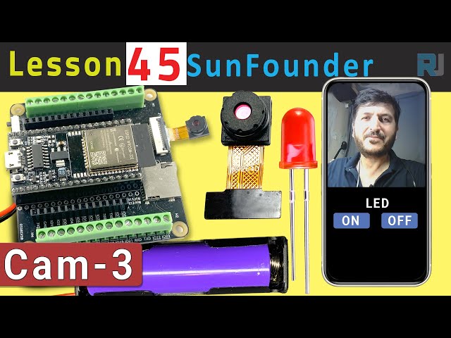
In this tutorial, we'll explore how to set up a custom streaming server using the ESP32 extension board from SunFounder. The project allows you to stream live video to your browser while also controlling an LED directly from the interface. This combination of features enables a hands-on learning experience with IoT and web technologies.
We'll be using the ESP32's built-in Wi-Fi capabilities to create a web server that streams video and handles LED control commands. The project involves coding, wiring, and understanding how the components interact. If you want a clearer understanding of the setup, be sure to check out the video at (in video at 00:00).
Hardware Explained
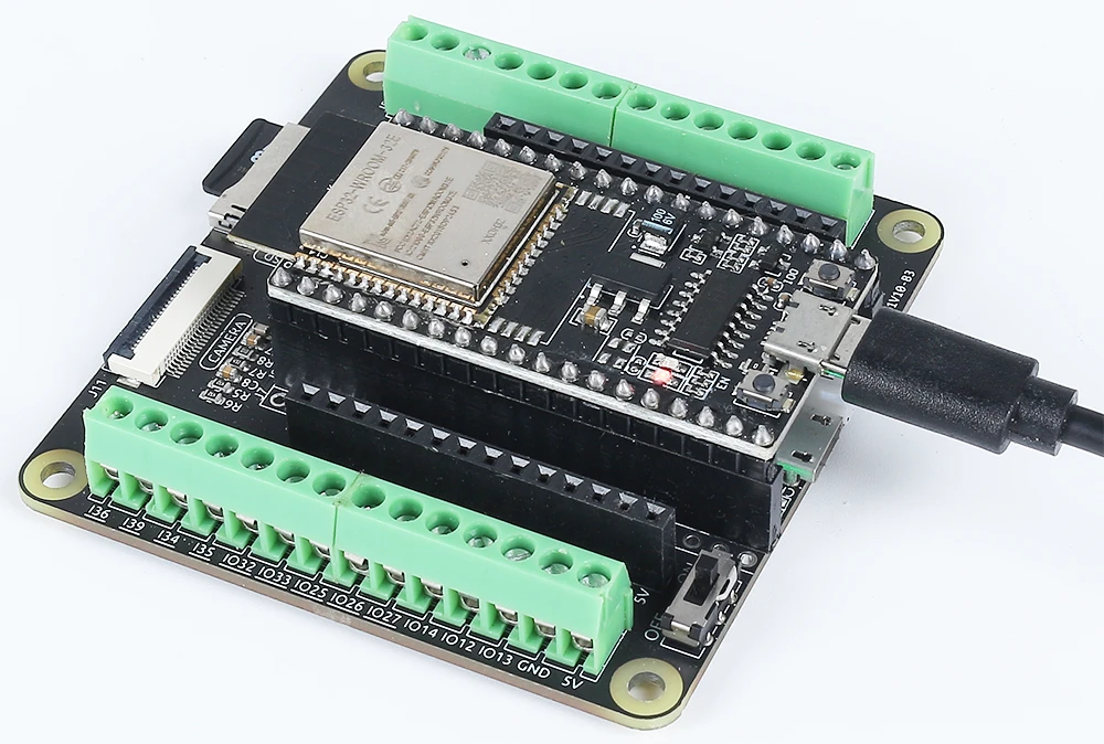
The main components for this project include the ESP32 microcontroller, a camera module, an LED, and a resistor. The ESP32 is a versatile microcontroller with built-in Wi-Fi and Bluetooth, making it perfect for IoT applications. The camera module allows us to capture video, while the LED provides a simple output device for control.
The LED is connected through a resistor to limit the current, preventing damage to both the LED and the microcontroller. This setup will allow us to turn the LED on and off via our web interface, showcasing the capabilities of the ESP32 in handling inputs and outputs over a network.
Datasheet Details
| Manufacturer | Espressif |
|---|---|
| Part number | ESP32-WROOM-32 |
| Logic/IO voltage | 3.3 V |
| Supply voltage | 3.0–3.6 V |
| Output current (per channel) | 12 mA |
| Peak current (per channel) | 40 mA |
| PWM frequency guidance | 1 kHz |
| Input logic thresholds | 0.2 V (low) / 0.8 V (high) |
| Voltage drop / RDS(on) / saturation | 0.2 V (typ.) |
| Thermal limits | Maximum junction temperature: 125 °C |
| Package | QFN48 |
| Notes / variants | Available in various configurations |
- Ensure the ESP32 is powered with a regulated 3.3 V supply.
- Use a current-limiting resistor (220 Ohm) with the LED to prevent damage.
- Maintain proper connections to avoid floating inputs.
- Check Wi-Fi credentials are correct and case-sensitive.
- Use a stable power source for consistent performance.
- Consider heat dissipation in enclosed spaces.
Wiring Instructions

To wire the ESP32 and the LED, start by connecting the longer pin of the LED to a suitable GPIO pin, in this case, we will use pin 14. The shorter pin should connect to the ground line on your breadboard. Next, place a 220 Ohm resistor in series with the LED, connecting one end to the GPIO pin (pin 14) and the other end to the ground. Ensure that the ESP32 is powered correctly, either through the micro USB port or with a 18650 lithium battery.
For the camera module, make sure to connect the necessary pins according to the camera model you are using, as the wiring may slightly vary. The ESP32 will handle the video stream via its built-in capabilities, and the LED control will be managed through the web interface we will set up in the code.
Code Examples & Walkthrough
The program begins by including necessary libraries and defining the Wi-Fi credentials. You will need to replace ssid and password with your actual Wi-Fi credentials to connect the ESP32 to your network.
const char* ssid = "SSID";
const char* password = "PASSWORD";
Next, we define the LED pin and set up the camera configurations. The pin used for the LED is defined as LED_PIN, which will be used later in the code to control the LED's state.
#define LED_PIN 14
pinMode(LED_PIN, OUTPUT);
In the request handler for the LED control, we check the command received from the web interface. Depending on whether the command is "on" or "off", we use digitalWrite(LED_PIN, 1); to turn the LED on and digitalWrite(LED_PIN, 0); to turn it off.
if(!strcmp(variable, "on")) {
Serial.println("ON");
digitalWrite(LED_PIN, 1);
}
else if(!strcmp(variable, "off")) {
Serial.println("OFF");
digitalWrite(LED_PIN, 0);
}
This logic allows the web interface to communicate effectively with the ESP32, enabling real-time control of the LED based on user interactions. The full code loads below the article for further exploration.
Demonstration / What to Expect
Once everything is set up and the code is uploaded, you should be able to access the ESP32's IP address in your web browser. The streaming video will appear, and you can control the LED using the buttons on the interface. Clicking "ON" will light up the LED, while "OFF" will turn it off. Make sure that the ESP32 and your computer are connected to the same network to ensure proper functionality (in video at 12:30).
Video Timestamps
- 00:00 Start
- 1:51 Introduction to project
- 2:31 Documentation page
- 3:33 Wiring Explained
- 5:08 Arduino code explained
- 13:28 Selecting ESP32 Board and COM port in Arduino IDE
- 15:10 Demonstration
/*
* 特此免费授予任何获得本软件及相关文档文件副本的人士使用权限。上述版权声明和此许可声明应包含在软件的所有副本或重要部分中。
*/
#include "esp_camera.h"
#include <WiFi.h>
#include "esp_timer.h"
#include "img_converters.h"
#include "Arduino.h"
#include "fb_gfx.h"
#include "soc/soc.h" // 禁用电压减少问题
#include "soc/rtc_cntl_reg.h" // 禁用电压减少问题
#include "esp_http_server.h"
// 用您的SSID/密码组合替换下列变量
const char* ssid = "SSID";
const char* password = "PASSWORD";
#define PART_BOUNDARY "123456789000000000000987654321"
#define CAMERA_MODEL_AI_THINKER
// #define CAMERA_MODEL_M5STACK_PSRAM
// #define CAMERA_MODEL_M5STACK_WITHOUT_PSRAM
// #define CAMERA_MODEL_M5STACK_PSRAM_B
// #define CAMERA_MODEL_WROVER_KIT
#if defined(CAMERA_MODEL_WROVER_KIT)
#define PWDN_GPIO_NUM -1
#define RESET_GPIO_NUM -1
#define XCLK_GPIO_NUM 21
#define SIOD_GPIO_NUM 26
#define SIOC_GPIO_NUM 27
#define Y9_GPIO_NUM 35
#define Y8_GPIO_NUM 34
#define Y7_GPIO_NUM 39
#define Y6_GPIO_NUM 36
#define Y5_GPIO_NUM 19
#define Y4_GPIO_NUM 18
#define Y3_GPIO_NUM 5
#define Y2_GPIO_NUM 4
#define VSYNC_GPIO_NUM 25
#define HREF_GPIO_NUM 23
#define PCLK_GPIO_NUM 22
#elif defined(CAMERA_MODEL_M5STACK_PSRAM)
#define PWDN_GPIO_NUM -1
#define RESET_GPIO_NUM 15
#define XCLK_GPIO_NUM 27
#define SIOD_GPIO_NUM 25
#define SIOC_GPIO_NUM 23
#define Y9_GPIO_NUM 19
#define Y8_GPIO_NUM 36
#define Y7_GPIO_NUM 18
#define Y6_GPIO_NUM 39
#define Y5_GPIO_NUM 5
#define Y4_GPIO_NUM 34
#define Y3_GPIO_NUM 35
#define Y2_GPIO_NUM 32
#define VSYNC_GPIO_NUM 22
#define HREF_GPIO_NUM 26
#define PCLK_GPIO_NUM 21
#elif defined(CAMERA_MODEL_M5STACK_WITHOUT_PSRAM)
#define PWDN_GPIO_NUM -1
#define RESET_GPIO_NUM 15
#define XCLK_GPIO_NUM 27
#define SIOD_GPIO_NUM 25
#define SIOC_GPIO_NUM 23
#define Y9_GPIO_NUM 19
#define Y8_GPIO_NUM 36
#define Y7_GPIO_NUM 18
#define Y6_GPIO_NUM 39
#define Y5_GPIO_NUM 5
#define Y4_GPIO_NUM 34
#define Y3_GPIO_NUM 35
#define Y2_GPIO_NUM 17
#define VSYNC_GPIO_NUM 22
#define HREF_GPIO_NUM 26
#define PCLK_GPIO_NUM 21
#elif defined(CAMERA_MODEL_AI_THINKER)
#define PWDN_GPIO_NUM 32
#define RESET_GPIO_NUM 33
#define XCLK_GPIO_NUM 0
#define SIOD_GPIO_NUM 26
#define SIOC_GPIO_NUM 27
#define Y9_GPIO_NUM 35
#define Y8_GPIO_NUM 34
#define Y7_GPIO_NUM 39
#define Y6_GPIO_NUM 36
#define Y5_GPIO_NUM 21
#define Y4_GPIO_NUM 19
#define Y3_GPIO_NUM 18
#define Y2_GPIO_NUM 5
#define VSYNC_GPIO_NUM 25
#define HREF_GPIO_NUM 23
#define PCLK_GPIO_NUM 22
#elif defined(CAMERA_MODEL_M5STACK_PSRAM_B)
#define PWDN_GPIO_NUM -1
#define RESET_GPIO_NUM 15
#define XCLK_GPIO_NUM 27
#define SIOD_GPIO_NUM 22
#define SIOC_GPIO_NUM 23
#define Y9_GPIO_NUM 19
#define Y8_GPIO_NUM 36
#define Y7_GPIO_NUM 18
#define Y6_GPIO_NUM 39
#define Y5_GPIO_NUM 5
#define Y4_GPIO_NUM 34
#define Y3_GPIO_NUM 35
#define Y2_GPIO_NUM 32
#define VSYNC_GPIO_NUM 25
#define HREF_GPIO_NUM 26
#define PCLK_GPIO_NUM 21
#else
#error "Camera model not selected"
#endif
#define LED_PIN 14
static const char* _STREAM_CONTENT_TYPE = "multipart/x-mixed-replace;boundary=" PART_BOUNDARY;
static const char* _STREAM_BOUNDARY = "\r\n--" PART_BOUNDARY "\r\n";
static const char* _STREAM_PART = "Content-Type: image/jpeg\r\nContent-Length: %u\r\n\r\n";
httpd_handle_t camera_httpd = NULL;
httpd_handle_t stream_httpd = NULL;
static const char PROGMEM INDEX_HTML[] = R"rawliteral(
<html>
<head>
<title>ESP32-CAM Robot</title>
<meta name="viewport" content="width=device-width, initial-scale=1">
<style>
body { font-family: Arial; text-align: center; margin:0px auto; padding-top: 30px;}
table { margin-left: auto; margin-right: auto; }
td { padding: 8 px; }
.button {
background-color: #2f4468;
border: none;
color: white;
padding: 10px 20px;
text-align: center;
text-decoration: none;
display: inline-block;
font-size: 18px;
margin: 6px 3px;
cursor: pointer;
-webkit-touch-callout: none;
-webkit-user-select: none;
-khtml-user-select: none;
-moz-user-select: none;
-ms-user-select: none;
user-select: none;
-webkit-tap-highlight-color: rgba(0,0,0,0);
}
img { width: auto ;
max-width: 100% ;
height: auto ;
transform: rotate(180deg);
}
</style>
</head>
<body>
<h1>ESP32 CAMERA</h1>
<img src="" id="photo" >
<table>
<tr><td align="center"><button class="button" onmousedown="toggleCheckbox('on');" ontouchstart="toggleCheckbox('on');onmouseup="toggleCheckbox('on');" ontouchend="toggleCheckbox('on');">ON</button></td>
<td align="center"><button class="button" onmousedown="toggleCheckbox('off');" ontouchstart="toggleCheckbox('off');onmouseup="toggleCheckbox('off');" ontouchend="toggleCheckbox('off');">OFF</button></td></tr>
</table>
<script>
function toggleCheckbox(x) {
var xhr = new XMLHttpRequest();
xhr.open("GET", "/action?go=" + x, true);
xhr.send();
}
window.onload = document.getElementById("photo").src = window.location.href.slice(0, -1) + ":81/stream";
</script>
</body>
</html>
)rawliteral";
static esp_err_t index_handler(httpd_req_t *req){
httpd_resp_set_type(req, "text/html");
return httpd_resp_send(req, (const char *)INDEX_HTML, strlen(INDEX_HTML));
}
static esp_err_t stream_handler(httpd_req_t *req){
camera_fb_t * fb = NULL;
esp_err_t res = ESP_OK;
size_t _jpg_buf_len = 0;
uint8_t * _jpg_buf = NULL;
char * part_buf[64];
res = httpd_resp_set_type(req, _STREAM_CONTENT_TYPE);
if(res != ESP_OK){
return res;
}
while(true){
fb = esp_camera_fb_get();
if (!fb) {
Serial.println("Camera capture failed");
res = ESP_FAIL;
} else {
if(fb->width > 400){
if(fb->format != PIXFORMAT_JPEG){
bool jpeg_converted = frame2jpg(fb, 80, &_jpg_buf, &_jpg_buf_len);
esp_camera_fb_return(fb);
fb = NULL;
if(!jpeg_converted){
Serial.println("JPEG compression failed");
res = ESP_FAIL;
}
} else {
_jpg_buf_len = fb->len;
_jpg_buf = fb->buf;
}
}
}
if(res == ESP_OK){
size_t hlen = snprintf((char *)part_buf, 64, _STREAM_PART, _jpg_buf_len);
res = httpd_resp_send_chunk(req, (const char *)part_buf, hlen);
}
if(res == ESP_OK){
res = httpd_resp_send_chunk(req, (const char *)_jpg_buf, _jpg_buf_len);
}
if(res == ESP_OK){
res = httpd_resp_send_chunk(req, _STREAM_BOUNDARY, strlen(_STREAM_BOUNDARY));
}
if(fb){
esp_camera_fb_return(fb);
fb = NULL;
_jpg_buf = NULL;
} else if(_jpg_buf){
free(_jpg_buf);
_jpg_buf = NULL;
}
if(res != ESP_OK){
break;
}
// Serial.printf("MJPG: %uB\n",(uint32_t)(_jpg_buf_len));
}
return res;
}
static esp_err_t cmd_handler(httpd_req_t *req){
char* buf;
size_t buf_len;
char variable[32] = {0,};
buf_len = httpd_req_get_url_query_len(req) + 1;
if (buf_len > 1) {
buf = (char*)malloc(buf_len);
if(!buf){
httpd_resp_send_500(req);
return ESP_FAIL;
}
if (httpd_req_get_url_query_str(req, buf, buf_len) == ESP_OK) {
if (httpd_query_key_value(buf, "go", variable, sizeof(variable)) == ESP_OK) {
} else {
free(buf);
httpd_resp_send_404(req);
return ESP_FAIL;
}
} else {
free(buf);
httpd_resp_send_404(req);
return ESP_FAIL;
}
free(buf);
} else {
httpd_resp_send_404(req);
return ESP_FAIL;
}
sensor_t * s = esp_camera_sensor_get();
int res = 0;
if(!strcmp(variable, "on")) {
Serial.println("ON");
digitalWrite(LED_PIN, 1);
}
else if(!strcmp(variable, "off")) {
Serial.println("OFF");
digitalWrite(LED_PIN, 0);
}
else {
res = -1;
}
if(res){
return httpd_resp_send_500(req);
}
httpd_resp_set_hdr(req, "Access-Control-Allow-Origin", "*");
return httpd_resp_send(req, NULL, 0);
}
void startCameraServer(){
httpd_config_t config = HTTPD_DEFAULT_CONFIG();
config.server_port = 80;
httpd_uri_t index_uri = {
.uri = "/",
.method = HTTP_GET,
.handler = index_handler,
.user_ctx = NULL
};
httpd_uri_t cmd_uri = {
.uri = "/action",
.method = HTTP_GET,
.handler = cmd_handler,
.user_ctx = NULL
};
httpd_uri_t stream_uri = {
.uri = "/stream",
.method = HTTP_GET,
.handler = stream_handler,
.user_ctx = NULL
};
if (httpd_start(&camera_httpd, &config) == ESP_OK) {
httpd_register_uri_handler(camera_httpd, &index_uri);
httpd_register_uri_handler(camera_httpd, &cmd_uri);
}
config.server_port += 1;
config.ctrl_port += 1;
if (httpd_start(&stream_httpd, &config) == ESP_OK) {
httpd_register_uri_handler(stream_httpd, &stream_uri);
}
}
void setup() {
WRITE_PERI_REG(RTC_CNTL_BROWN_OUT_REG, 0); // 禁用电压下降检测器
pinMode(LED_PIN, OUTPUT);
Serial.begin(115200);
Serial.setDebugOutput(false);
camera_config_t config;
config.ledc_channel = LEDC_CHANNEL_0;
config.ledc_timer = LEDC_TIMER_0;
config.pin_d0 = Y2_GPIO_NUM;
config.pin_d1 = Y3_GPIO_NUM;
config.pin_d2 = Y4_GPIO_NUM;
config.pin_d3 = Y5_GPIO_NUM;
config.pin_d4 = Y6_GPIO_NUM;
config.pin_d5 = Y7_GPIO_NUM;
config.pin_d6 = Y8_GPIO_NUM;
config.pin_d7 = Y9_GPIO_NUM;
config.pin_xclk = XCLK_GPIO_NUM;
config.pin_pclk = PCLK_GPIO_NUM;
config.pin_vsync = VSYNC_GPIO_NUM;
config.pin_href = HREF_GPIO_NUM;
config.pin_sscb_sda = SIOD_GPIO_NUM;
config.pin_sscb_scl = SIOC_GPIO_NUM;
config.pin_pwdn = PWDN_GPIO_NUM;
config.pin_reset = RESET_GPIO_NUM;
config.xclk_freq_hz = 20000000;
config.pixel_format = PIXFORMAT_JPEG;
if(psramFound()){
config.frame_size = FRAMESIZE_VGA;
config.jpeg_quality = 10;
config.fb_count = 2;
} else {
config.frame_size = FRAMESIZE_SVGA;
config.jpeg_quality = 12;
config.fb_count = 1;
}
// 相机初始化
esp_err_t err = esp_camera_init(&config);
if (err != ESP_OK) {
Serial.printf("Camera init failed with error 0x%x", err);
return;
}
// Wi-Fi连接
WiFi.begin(ssid, password);
while (WiFi.status() != WL_CONNECTED) {
delay(500);
Serial.print(".");
}
Serial.println("");
Serial.println("WiFi connected");
Serial.print("Camera Stream Ready! Go to: http: // ");
Serial.println(WiFi.localIP());
// 开始流媒体网络服务器
startCameraServer();
}
void loop() {
}
Common Course Links
Common Course Files
资源与参考
-
文档ESP32教程45/55- SunFounder自定义流媒体服务器文档页docs.sunfounder.com
文件📁
没有可用的文件。