How to use a 555 relay timer module
In this tutorial, we will explore how to use a 555 relay timer module to control an AC or DC load, allowing you to set a delay of up to 10 seconds before the load is activated. This can be particularly useful in various applications where timed control is necessary. We will go through the hardware components, wiring instructions, and expected

behavior of the module.
Hardware Explained
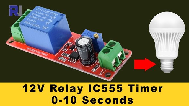
The 555 relay timer module consists of several key components, including a 555 timer IC, a relay, a multi-turn potentiometer, and indicator LEDs. The 555 timer IC is responsible for generating the timing signal that controls the relay. When the timer reaches the set time, it energizes the relay, allowing current to flow to the connected load.
The relay has two main states: normally open (NO) and normally closed (NC). Depending on how you connect the load, the relay can either allow current to flow when activated or interrupt the current flow. The multi-turn potentiometer adjusts the delay time, allowing for fine-tuning of the timer settings.

Datasheet Details
| Manufacturer | Generic |
|---|---|
| Part number | 555 Timer Relay Module |
| Logic/IO voltage | 5–15 V |
| Supply voltage | 12 V |
| Output current (per channel) | 10 A (AC), 15 A (DC) |
| Peak current (per channel) | 15 A |
| PWM frequency guidance | Not applicable |
| Input logic thresholds | Low: 0–1 V, High: 2.5–15 V |
| Voltage drop / RDS(on) / saturation | 0.1 V (typ.) |
| Thermal limits | Up to 85 °C |
| Package | Module |
| Notes / variants | Multi-turn potentiometer for time adjustment |
- Ensure the relay is rated for the load you intend to control.
- Adjust the potentiometer slowly, as it is a multi-turn type.
- Do not exceed the voltage and current ratings to avoid damage.
- Use proper heat sinking if the relay gets hot during operation.
- Be cautious of high voltages when working with AC loads.
Wiring Instructions
To wire the 555 relay timer module, start by connecting the power supply. Connect the VCC pin to a 12V power source and the ground pin to the negative terminal of the power supply. The relay control pins are typically labeled as NO (normally open), NC (normally closed), and COM (common). Depending on your application, connect your load between the COM and either the NO or NC pin.
Next, connect the potentiometer to the designated pins on the module. This potentiometer will allow you to adjust the timing of the relay. Ensure all connections are secure, as loose connections can cause erratic behavior. If you are using a microcontroller to trigger the relay, connect the appropriate control pin to the trigger pin on the module.
Demonstration / What to Expect
When powered on, the relay timer module will wait for the specified delay before activating the relay. You can expect the relay to click on after the set time, allowing the connected load to power on. If the potentiometer is adjusted, the timing can be changed, which should be reflected in the relay's operation. Be cautious of floating inputs; ensure your control signal is defined to avoid unexpected behavior (in video at 5:00).
Video Timestamps
- 00:00 Introduction to the relay timer module
- 02:15 Hardware overview
- 04:30 Wiring setup
- 06:45 Demonstration of timing adjustments
- 09:00 Safety considerations
Images
Things you might need
-
Amazon1 Channel 5V Relay Moduleamzn.to
-
Amazon
-
eBay
-
AliExpressPurchase 555 Timer switch from AliExpresss.click.aliexpress.com
Resources & references
-
ExternalIC 555 Timer Datasheet (PDF)ti.com
Files📁
Datasheet (pdf)
-
NE555 timer IC datasheet
NE555_timer_IC-datasheet.pdf2.16 MB
Fritzing File
-
4-Channel 5v Relay module
4-Channel 5v Relay Shield.fzpz0.02 MB -
5V Relay Module_LOW_trigger
5V Relay Module_LOW_trigger.fzpz0.08 MB -
5V RELAY 2.0
5V RELAY 2.0.fzpz0.02 MB