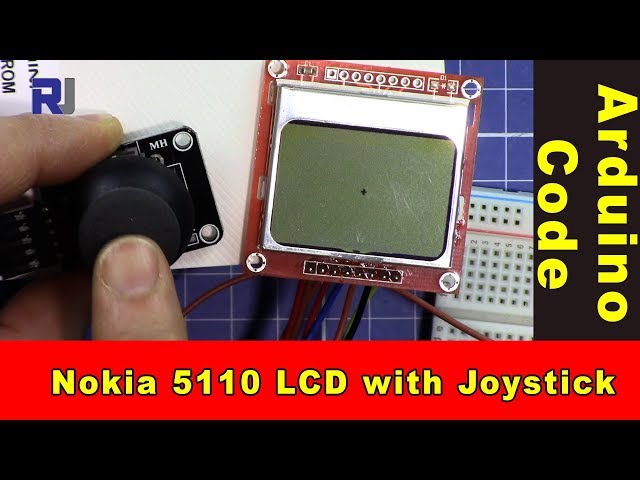
Arduino code to use a dual-axis XY joystick with a Nokia 5110 LCD screen
This tutorial will guide you through the process of using a dual-axis XY joystick to control a dot displayed on a Nokia 5110 LCD screen. The project involves reading the joystick's position and updating the display accordingly. By the end of this guide, you will have a functional setup where moving the joystick alters the position of a dot on the screen (in video at 00:00).

In this project, you will utilize the joystick's analog outputs to determine its position on the X and Y axes. The readings from the joystick will be mapped to the dimensions of the LCD screen, allowing for smooth movement of the dot. Additionally, you'll learn how to read the joystick's switch input, which can be used for further interactions.
Hardware Explained
The primary components for this project include the Arduino, the dual-axis XY joystick, and the Nokia 5110 LCD screen. The Arduino serves as the microcontroller, processing inputs from the joystick and controlling the LCD display.
The joystick typically has two potentiometers—one for the X-axis and one for the Y-axis. As you move the joystick, these pots change resistance, sending varying voltage levels to the Arduino's analog input pins. The Nokia 5110 LCD screen is controlled via SPI communication, which allows for efficient data transfer and display updates.
Datasheet Details
| Manufacturer | Texas Instruments |
|---|---|
| Part number | L293D |
| Logic/IO voltage | 5 V |
| Supply voltage | 4.5–36 V |
| Output current (per channel) | 600 mA |
| Peak current (per channel) | 1.2 A |
| PWM frequency guidance | 20 kHz |
| Input logic thresholds | TTL compatible |
| Voltage drop / RDS(on) / saturation | 1.5 V max |
| Thermal limits | 150 °C |
| Package | DIP-16 |
| Notes / variants | Widely used in motor driver applications |
- Ensure proper heat-sinking for continuous operation.
- Use decoupling capacitors for stable power supply.
- Check voltage ratings to avoid damaging the components.
- Be cautious with PWM signals; ensure they are within specified limits.
- Verify wiring connections to avoid short circuits.
Wiring Instructions

To wire the joystick and LCD screen to the Arduino, start by connecting the joystick's VCC pin to the Arduino's 5V and the GND pin to the Arduino's GND. Connect the joystick's X-axis output to analog pin A0 and the Y-axis output to analog pin A1. The joystick's switch output should be connected to digital pin 2.
For the Nokia 5110 LCD, connect the following pins: VCC to 5V, GND to GND, SCE to pin 7, RST to pin 6, D/C to pin 5, DN(MOSI) to pin 11, and SCLK to pin 13. Lastly, connect the LED pin through a 330 Ohm resistor to pin 9 for backlight control.
Code Examples & Walkthrough
In the setup function, we initialize the serial communication and the LCD. The command lcdBegin() sets up the pins and initializes the display. The contrast is set for optimal visibility.
void setup() {
  Serial.begin(9600);
  lcdBegin();
  setContrast(40);
  delay(1000);
  clearDisplay(BLACK);
  updateDisplay();
}
This initializes the necessary components for the project, ensuring that the LCD is ready to display information.

In the loop function, we read the joystick's position and map it to the screen dimensions. The dot's position is updated based on the joystick's X and Y values.
void loop() {
  int x = analogRead(A0); // read the x position of joystick
  int y = analogRead(A1); // read the y position of joystick
  int xPos = map(x, 0, 1023, 0, screenWidth); // map x to screen
  int yPos = map(y, 0, 1023, 0, screenHeight); // map y to screen
  setCircle(xPos, yPos, thickness, BLACK, 2); // display the dot
  updateDisplay();
  delay(10);
}
This code continuously updates the position of the dot on the LCD based on the joystick's movement.
Demonstration / What to Expect
When you power up the circuit, the LCD will display a dot. Moving the joystick will reposition the dot in real-time according to the joystick's X and Y movements. If the joystick switch is pressed, it can trigger additional functionalities that you may implement. Be aware of potential floating inputs if the joystick is not centered, which could lead to unexpected dot movements (in video at 01:30).
Video Timestamps
- 00:00 - Introduction to the project
- 01:30 - Wiring explanation
- 02:45 - Code walkthrough
- 04:10 - Demonstration of functionality
Изображения
/*
 * This is Arduino code to use a dual-axis XY joystick with a Nokia 5110 screen to move a dot on the screen.
 * It also reads the switch.
 * Other Arduino libraries and videos: https://robojax.com

 * Watch the video for this code to learn it fully.
  * Watch the video here: https://youtu.be/zqDZybR5JSE
 * This code is offered "as is" without any warranty.
 * If you are sharing this code, you must keep this copyright note.
 */
 /*
/* Nokia 5100 LCD Example Code with Added Joystick by Robojax
   Graphics driver and PCD8544 interface code for SparkFun's
   84x48 Graphic LCD.
   https://www.sparkfun.com/products/10168
   Original source code:
https://github.com/sparkfun/GraphicLCD_Nokia_5110

  This stuff could all be put into a library, but we wanted to
  leave it all in one sketch to keep it as transparent as possible.

  Hardware: (Note most of these pins can be swapped)
    Graphic LCD Pin ---------- Arduino Pin
       1-VCC       ----------------  5V
       2-GND       ----------------  GND
       3-SCE       ----------------  7
       4-RST       ----------------  6
       5-D/C       ----------------  5
       6-DN(MOSI)  ----------------  11
       7-SCLK      ----------------  13
       8-LED       - 330 Ohm res --  9
   The SCLK, DN(MOSI), must remain where they are, but the other
   pins can be swapped. The LED pin should remain a PWM-capable
   pin. Don't forget to stick a current-limiting resistor in line
   between the LCD's LED pin and Arduino pin 9!
   Modified by Ahmad S. for Robojax.com
   on Mar 11, 2018 at 20:49 at Ajax, Ontario, Canada
*/
#include <SPI.h>
#include "LCD_Functions.h"

#define sw 2 // pint 2 is used for joystick switch input
#define screenWidth 83 // NOkia screen width
#define screenHeight 47 // Nokia screen height
int thickness =1;// the thickness of the dot


void setup()
{
  // Robojax Dual Axis joystick  with Nokia 5110 LCD screen project
  Serial.begin(9600);

  lcdBegin(); // This will setup our pins, and initialize the LCD
  //updateDisplay(); // with displayMap untouched, SFE logo
  setContrast(40); // Good values range from 40-60
  delay(1000);

  clearDisplay(BLACK);
  updateDisplay();
}


void loop()
{
  clearDisplay(WHITE);
   // Robojax Dual Axis joystick  with Nokia 5110 LCD screen project
  int x = analogRead(A0);// read the x position of joystick
  int y = analogRead(A1); // read the y position of joystick
  int xPos = map(x, 0, 1023,0,screenWidth);// map or translate the x of joystick to x of screen
  int yPos = map(y, 0, 1023,0,screenHeight); // map or translate the y of joystick to y of screen
  int sStat = digitalRead(sw);//read the switch from pin 2
  Serial.print("X: ");
  Serial.print(xPos);
  Serial.print(" Y: ");
  Serial.println(yPos);// Robojax prints y

  // Robojax Dual Axis joystick  with Nokia 5110 LCD screen project
   //setCircle(xPos, yPos, thicness, BLACK, 2);
   // xPos is the position of x
   // yPos is the position of y
   // thickness
  setCircle(xPos, yPos, thickness, BLACK, 2);// display the dot on the screen
    updateDisplay();
  delay(10);


}
Вещи, которые могут вам понадобиться
-
АмазонкаКупите джойстик XY на Amazon.amzn.to
-
Амазонка
Ресурсы и ссылки
Ресурсов пока нет.
Файлы📁
Требуемый файл (.h)
-
robojax-nokia5110.h header file for Arduino
robojax-nokia5110.zip0.01 MB -
LCD_Functions. file for Nokia
LCD_Functions.h0.02 MB
Файл Fritzing
-
Nokia 5110 LCD
Nokia_5110_LCD.fzpz0.03 MB -
Black Joystick KY-023
Black Joystick KY-023.fzpz0.02 MB