Nokia 5110 LCD画面で二軸(XY)ジョイスティックを使用するための Arduino コード
このチュートリアルでは、二軸のXYジョイスティックを使用してNokia 5110 LCD画面に表示される点を制御する手順を案内します。プロジェクトではジョイスティックの位置を読み取り、それに応じて表示を更新します。本ガイドの最後には、ジョイスティックを動かすことで画面上の点の位置が変わる動作するセットアップができあがります(ビデオでは00:00)。

このプロジェクトでは、ジョイスティックのアナログ出力を利用してX軸およびY軸上での位置を判定します。ジョイスティックの読み取り値はLCD画面のサイズにマッピングされ、ドットが滑らかに移動するようになります。さらに、ジョイスティックのスイッチ入力の読み取り方法も学び、それを用いて追加の操作を行うことができます。
ハードウェア解説
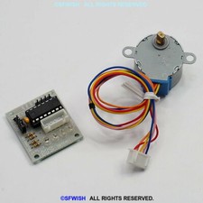
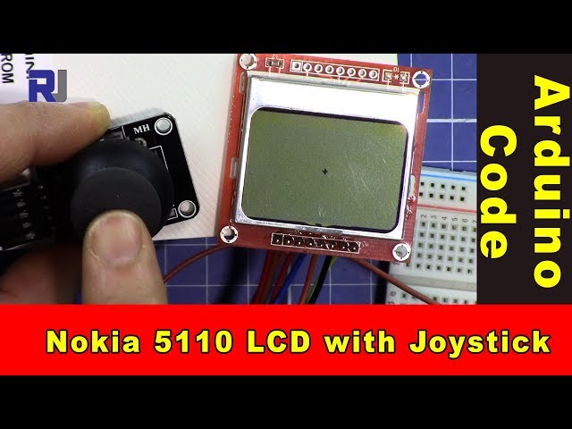
このプロジェクトの主要な構成要素は、Arduino、デュアル軸(XY)ジョイスティック、およびNokia 5110 LCDディスプレイです。Arduinoはマイクロコントローラとして機能し、ジョイスティックからの入力を処理してLCDディスプレイを制御します。
ジョイスティックには通常、X軸用とY軸用の2つのポテンショメーターがあります。ジョイスティックを動かすと、これらのポテンショメーターは抵抗値を変化させ、その結果としてさまざまな電圧レベルがArduinoのアナログ入力ピンに送られます。Nokia 5110のLCD画面はSPI通信で制御されており、効率的なデータ転送と表示の更新が可能です。
データシートの詳細
| 製造業者 | テキサス・インスツルメンツ |
|---|---|
| 部品番号 | L293D |
| ロジック/入出力電圧 | 5 V |
| 電源電圧 | 4.5〜36V |
| 出力電流(チャンネルごと) | 600 mA |
| ピーク電流(チャンネルごと) | 1.2 A |
| PWM周波数に関するガイダンス | 20 kHz |
| 入力論理閾値 | TTL互換 |
| 電圧降下 / Rドレイン・ソース(オン) / 彩度 | 最大1.5V |
| 熱制限 | 150℃ |
| パッケージ | DIP-16 |
| 備考 / バリエーション | モータドライバ用途で広く使用されている |
- 連続運転時は、適切な放熱対策を確実に行ってください。
- 安定した電源供給のためにデカップリングコンデンサを使用してください。
- 部品を損傷させないよう、定格電圧を確認してください。
- PWM信号には注意し、指定された範囲内にあることを確認してください。
- 短絡を避けるために配線の接続を確認してください。
配線手順

ジョイスティックとLCDスクリーンをArduinoに配線するには、まずジョイスティックのVCCピンをArduinoの5Vに、GNDピンをArduinoのGNDに接続します。ジョイスティックのX軸出力をアナログピンに接続しますA0そしてY軸の出力をアナログピンに接続するA1ジョイスティックのスイッチ出力はデジタルピンに接続する必要があります。2.
Nokia 5110 LCDでは、以下のピンを接続します: VCC を 5V に、GND を GND に、SCE を ピンに7, RSTをピンに6、D/Cをピンに5, DN(MOSI) をピンに11、およびSCLKをピンに13最後に、LEDピンを330Ωの抵抗器を介してピンに接続します9バックライト制御用。
コード例と解説
setup関数では、シリアル通信とLCDを初期化します。コマンドlcdBegin()ピンを設定し、ディスプレイを初期化します。コントラストは視認性が最適になるように設定されています。
void setup() {
  Serial.begin(9600);
  lcdBegin();
  setContrast(40);
  delay(1000);
  clearDisplay(BLACK);
  updateDisplay();
}
これによりプロジェクトに必要なコンポーネントが初期化され、LCDが情報を表示できる状態になります。

loop 関数では、ジョイスティックの位置を読み取り、それを画面のサイズにマッピングします。ドットの位置はジョイスティックのXおよびYの値に基づいて更新されます。
void loop() {
  int x = analogRead(A0); // read the x position of joystick
  int y = analogRead(A1); // read the y position of joystick
  int xPos = map(x, 0, 1023, 0, screenWidth); // map x to screen
  int yPos = map(y, 0, 1023, 0, screenHeight); // map y to screen
  setCircle(xPos, yPos, thickness, BLACK, 2); // display the dot
  updateDisplay();
  delay(10);
}
このコードはジョイスティックの動きに応じてLCD上のドットの位置を継続的に更新します。
デモンストレーション/何を期待できるか
回路に電源を入れると、LCDにドットが表示されます。ジョイスティックを動かすと、ドットはジョイスティックのX軸およびY軸の動きに応じてリアルタイムで移動します。ジョイスティックのスイッチを押すと、実装次第で追加の機能を起動させることができます。ジョイスティックが中央にない場合、入力がフローティング状態になり、予期しないドットの動きが発生する可能性があることに注意してください(ビデオの01:30)。
動画のタイムスタンプ
- 00:00- プロジェクトの紹介
- 01:30- 配線の説明
- 午前02:45- コードのウォークスルー
- 04:10- 機能の実演
画像
/*
 * This is Arduino code to use a dual-axis XY joystick with a Nokia 5110 screen to move a dot on the screen.
 * It also reads the switch.
 * Other Arduino libraries and videos: https://robojax.com

 * Watch the video for this code to learn it fully.
  * Watch the video here: https://youtu.be/zqDZybR5JSE
 * This code is offered "as is" without any warranty.
 * If you are sharing this code, you must keep this copyright note.
 */
 /*
/* Nokia 5100 LCD Example Code with Added Joystick by Robojax
   Graphics driver and PCD8544 interface code for SparkFun's
   84x48 Graphic LCD.
   https://www.sparkfun.com/products/10168
   Original source code:
https://github.com/sparkfun/GraphicLCD_Nokia_5110

  This stuff could all be put into a library, but we wanted to
  leave it all in one sketch to keep it as transparent as possible.

  Hardware: (Note most of these pins can be swapped)
    Graphic LCD Pin ---------- Arduino Pin
       1-VCC       ----------------  5V
       2-GND       ----------------  GND
       3-SCE       ----------------  7
       4-RST       ----------------  6
       5-D/C       ----------------  5
       6-DN(MOSI)  ----------------  11
       7-SCLK      ----------------  13
       8-LED       - 330 Ohm res --  9
   The SCLK, DN(MOSI), must remain where they are, but the other
   pins can be swapped. The LED pin should remain a PWM-capable
   pin. Don't forget to stick a current-limiting resistor in line
   between the LCD's LED pin and Arduino pin 9!
   Modified by Ahmad S. for Robojax.com
   on Mar 11, 2018 at 20:49 at Ajax, Ontario, Canada
*/
#include <SPI.h>
#include "LCD_Functions.h"

#define sw 2 // pint 2 is used for joystick switch input
#define screenWidth 83 // NOkia screen width
#define screenHeight 47 // Nokia screen height
int thickness =1;// the thickness of the dot


void setup()
{
  // Robojax Dual Axis joystick  with Nokia 5110 LCD screen project
  Serial.begin(9600);

  lcdBegin(); // This will setup our pins, and initialize the LCD
  //updateDisplay(); // with displayMap untouched, SFE logo
  setContrast(40); // Good values range from 40-60
  delay(1000);

  clearDisplay(BLACK);
  updateDisplay();
}


void loop()
{
  clearDisplay(WHITE);
   // Robojax Dual Axis joystick  with Nokia 5110 LCD screen project
  int x = analogRead(A0);// read the x position of joystick
  int y = analogRead(A1); // read the y position of joystick
  int xPos = map(x, 0, 1023,0,screenWidth);// map or translate the x of joystick to x of screen
  int yPos = map(y, 0, 1023,0,screenHeight); // map or translate the y of joystick to y of screen
  int sStat = digitalRead(sw);//read the switch from pin 2
  Serial.print("X: ");
  Serial.print(xPos);
  Serial.print(" Y: ");
  Serial.println(yPos);// Robojax prints y

  // Robojax Dual Axis joystick  with Nokia 5110 LCD screen project
   //setCircle(xPos, yPos, thicness, BLACK, 2);
   // xPos is the position of x
   // yPos is the position of y
   // thickness
  setCircle(xPos, yPos, thickness, BLACK, 2);// display the dot on the screen
    updateDisplay();
  delay(10);


}
必要かもしれないもの
-
アマゾンAmazonでNokia 5110のLCDを購入するamzn.to
-
アマゾンAmazonでXYジョイスティックを購入してください。amzn.to
リソースと参考文献
まだリソースはありません。
ファイル📁
必要なファイル (.h)
-
robojax-nokia5110.h header file for Arduino
robojax-nokia5110.zip0.01 MB -
LCD_Functions. file for Nokia
LCD_Functions.h0.02 MB
フリッツィングファイル
-
ノキア5110 LCD
Nokia_5110_LCD.fzpz0.03 MB -
ブラックジョイスティック KY-023
Black Joystick KY-023.fzpz0.02 MB