YX850 Power Failure Automatic Switching Standby Battery Lithium Battery Module 5V-48V Emergency UPS
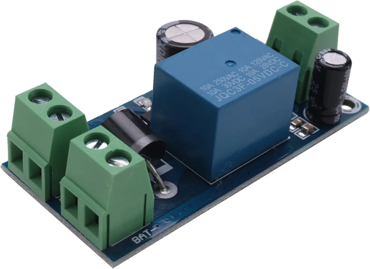
This guide reviews two automatic battery backup modules from Robojax: the YX-X801 and the YX-X850. These are not traditional uninterruptible power supplies (UPS), as they introduce a brief 0.7-second delay during the switchover. Instead, they serve as automatic transfer switches, seamlessly connecting your DC load to either a main power supply or a backup battery. This makes them incredibly useful for a wide range of DIY electronics projects where a brief power interruption is acceptable.
Here are some practical applications for these modules:
- Security Systems: Keeping IP cameras, alarm panels, and electronic locks powered during a power outage.
- Networking Equipment: Providing backup power to routers, switches, and network-attached storage (NAS) devices to maintain connectivity.
- Embedded Projects: Ensuring a microcontroller (like an ESP32 or Arduino) or a single-board computer (like a Raspberry Pi) shuts down gracefully or continues operating during a blackout.
- Automation & Sensors: Powering smart home hubs, sensor nodes, and environmental monitoring stations that need to remain active.
- Aquarium & Hydroponics: Keeping air pumps and critical filtration systems running during short power interruptions.
This guide will explain the key differences between the two modules, how they work, and how to wire them for your specific project.
Hardware Overview
Let's break down the two modules reviewed in the video. The primary difference lies in their operating voltage range and their ability to charge a battery.
YX-X801 Module
The YX-X801 is a straightforward automatic transfer switch. It is designed to work with a simple DC power supply and a battery of the same voltage.
- Operating Voltage: 12V to 48V DC. The module uses an internal buck converter to power its relay, which requires a minimum of 12V.
- Maximum Load Current: 10 Amps.
- Battery Charging: No. This module does not have a charging circuit. It requires a separate, dedicated power supply.
YX-X850 Module
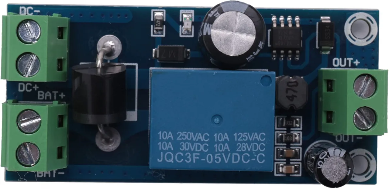
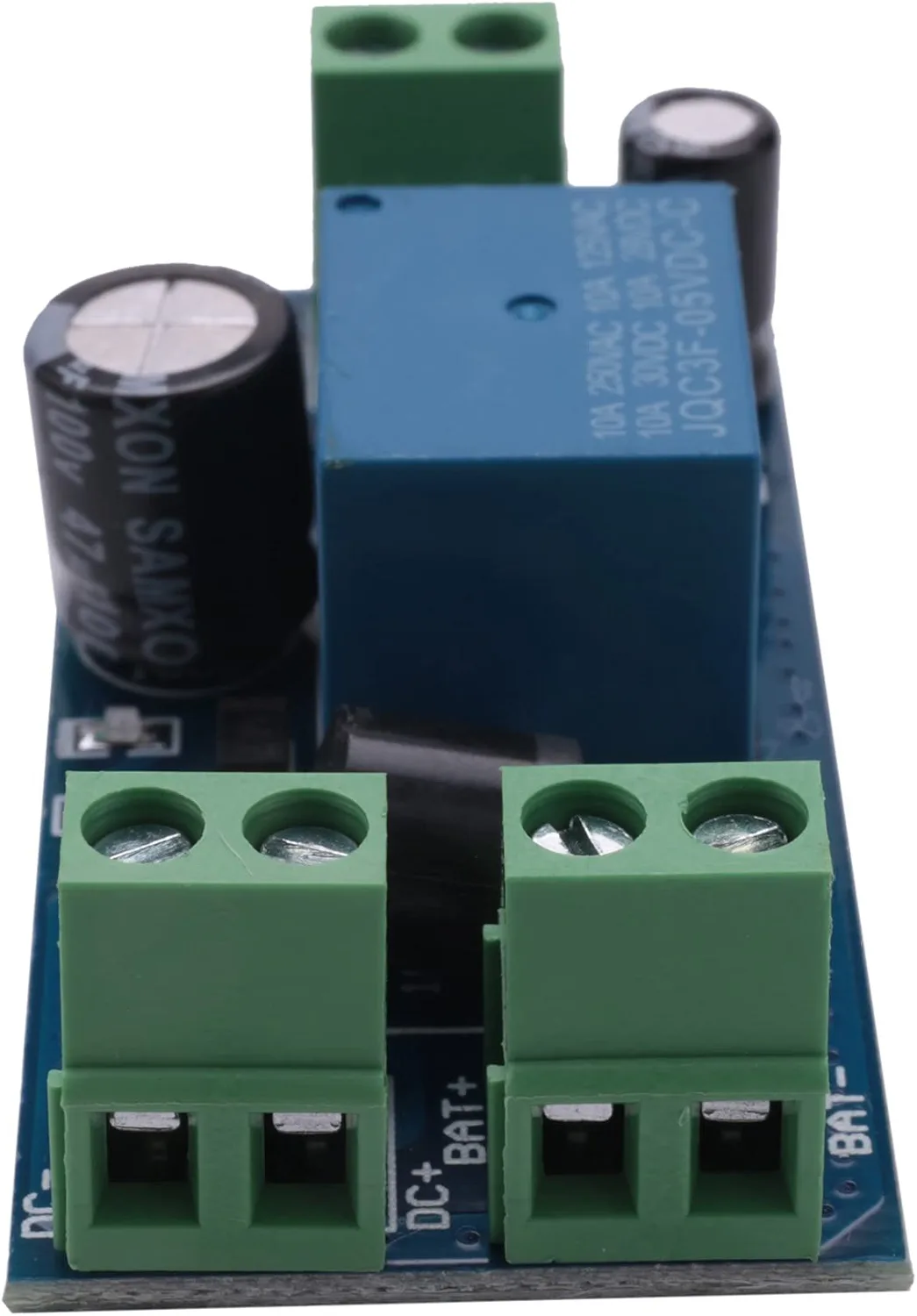
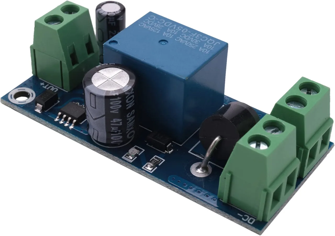
The YX-X850 is a more versatile version that includes a diode, allowing it to be used with a battery charger. This enables it to charge the battery while simultaneously powering the load from the main power source.
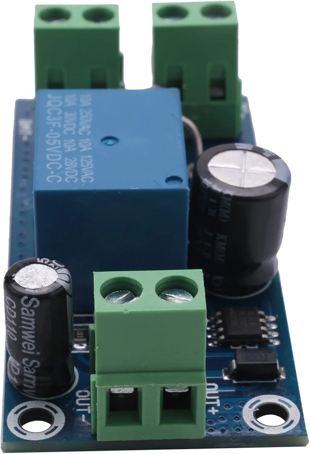
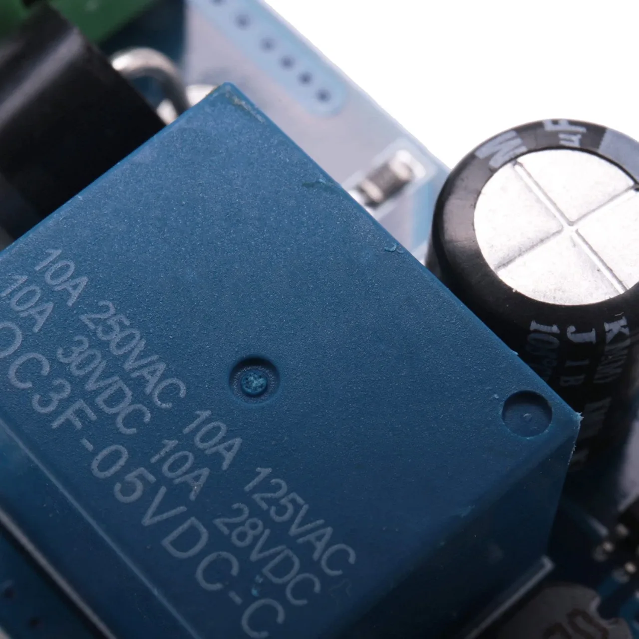
- Operating Voltage: 5V to 48V DC. The relay in this module is a 5V relay, allowing for a lower minimum voltage.
- Maximum Load Current: 10 Amps.
- Battery Charging: Yes. It can be used with a battery charger to charge the battery. The built-in 10A diode prevents the battery from discharging back into the charger.
Both modules feature an LED indicator that shows the status of the main power supply and a relay that performs the switching action. The modules also include a buck converter (an XL7005) to step down the input voltage to a level suitable for the relay coil.
Wiring Guide
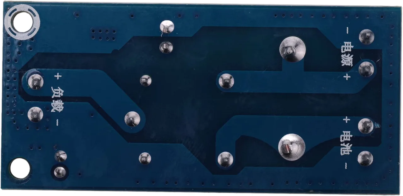
Wiring these modules is straightforward. The negative terminals for the power supply, battery, and load are all common and connected internally. The relay only switches the positive line. (in video at 06:57)
Here is the wiring diagram for both modules:
Connecting the YX-X801
For the YX-X801, you will connect your main DC power supply and your battery to the module. The voltage of your power supply and battery must match the voltage of your load.
- Connect your main DC power supply to the "Power Supply" or "DC IN" terminals, observing the correct polarity.
- Connect your backup battery to the "Battery" terminals.
- Connect your load to the "Load" or "Output" terminals.
Connecting the YX-X850 with a Charger
For the YX-X850, you can use a battery charger instead of a simple power supply. This setup allows the module to charge the battery when main power is available.
- Connect your battery charger to the "Power Supply" or "DC IN" terminals. The charger's voltage must match your battery's voltage.
- Connect your battery to the "Battery" terminals.
- Connect your load to the "Load" or "Output" terminals.
How It Works
The core of the module is a relay, which acts as a switch. When the main power is present, the relay is energized, connecting the load to the main power source. When the main power fails, the relay is de-energized, and its switch connects the load to the battery. (in video at 04:29)
This switching action is not instantaneous. The relay has a mechanical delay of approximately 0.7 seconds. This is why the module is not considered a true UPS. Your device will experience a brief power interruption during the switchover.
In the YX-X850, a high-current diode is placed between the main power input and the battery terminal. This diode allows current to flow from the charger to the battery, but prevents the battery from discharging back into the charger when the main power is off. This feature is what enables the module to charge the battery. (in video at 05:54)
Testing and Demonstration
In the video, the modules were tested with a 12V battery and a load consisting of two 12V bulbs connected in series to handle a higher voltage. The test demonstrated the following:
- Normal Operation: With the main power supply connected, the load was powered by it, and the LED indicator was on. (in video at 09:12)
- Power Failure: When the main power was disconnected, the relay clicked, and the load switched to the battery. The current draw was measured at around 390mA, slightly higher than the 375mA from the power supply due to the lower battery voltage. (in video at 09:42)
- Voltage Variation: The input voltage was increased to 24V, and the module continued to operate correctly, with the bulbs shining brighter. (in video at 11:03)
- YX-X850 Charging: When the YX-X850 was tested with a charger, the current from the power supply was measured at 989mA. This is the sum of the load current (~350mA) and the battery charging current. When the main power was disconnected, the current dropped to 401mA, which is the load current drawn from the battery. (in video at 12:11)
Conclusion
The YX-X801 and YX-X850 are simple and effective solutions for adding automatic battery backup to your DC projects. They are not true UPS units due to the 0.7-second relay delay, but they are perfect for applications where a brief interruption is acceptable. The YX-X850's ability to work with a charger makes it a more complete solution, as it can maintain your battery's charge automatically. Always ensure your power supply, battery, and load voltages are properly matched for safe and reliable operation.
Video Chapters
- [00:00] Introduction to the YX-X801 and YX-X850 Modules
- [01:46] YX-850 Module Specifications and Features
- [02:29] YX-X850 Module Specifications and Features
- [03:23] YX-X801 Module Details and Operation
- [05:32] YX-X850 Module Details and Battery Charging
- [08:41] Testing the YX-X801 with a 12V Load
- [12:01] Testing the YX-X850 with a Battery Charger
Images
Things you might need
-
Amazon
-
Amazon
-
BanggoodYX850 Power Failure Automatic on Banggoodbanggood.com
Resources & references
No resources yet.
Files📁
No files available.