Lesson 30/31: Car-8 Line Tracking by Smart Car from SunFounder Arduino Kit | Robojax
This guide walks you through building a line-following smart car using the SunFounder 3-in-1 Arduino kit.
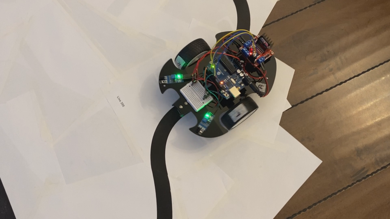
The project, demonstrated in the video, uses an infrared line tracking module to detect a black line on a white surface and control two motors to keep the car on track. This is a fundamental robotics project that teaches you about sensor reading, conditional logic, and motor control. The real-world value is immense—it's the basis for automated guided vehicles (AGVs) in warehouses, robotic vacuum cleaners that follow room edges, and educational platforms for learning about autonomous navigation. Beyond the basic build, you can use this concept for:
- Creating a simple robot that can navigate a predefined path in a maze or on a track.
- Building an automated delivery cart for a small office or lab.
- Developing a line-following robot for a school science project or competition.
- Prototyping a system for an industrial conveyor belt that sorts items based on position.
Hardware and Components
The core of this project is the line tracking module, which uses an infrared (IR) transmitter and receiver pair. Here's a breakdown of the key components:
- Line Tracking Module (TCRT5000): This sensor emits infrared light and measures the reflected intensity. The module includes an LM393 comparator to convert the analog signal into a digital HIGH or LOW output.
- Smart Car Chassis with Motors: The SunFounder kit includes a car frame with two geared motors, which are controlled by the Arduino to steer the vehicle.
- Arduino Board: The "brain" of the operation, reading the sensor and sending commands to the motors.
- Motor Driver (on the car's shield): This circuit allows the Arduino's low-power pins to control the higher-current motors.
Wiring Guide
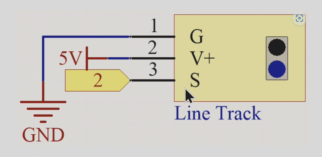
The wiring for the line tracking module is straightforward. The video demonstrates the connections as follows (in video at 04:04):
- Line Tracker VCC (middle pin): Connect to the Arduino's 5V pin.
- Line Tracker GND (left pin): Connect to the Arduino's GND pin.
- Line Tracker OUT (right pin): Connect to the Arduino's digital pin 2.
The motors are connected to the motor driver on the car's shield. In the code, the right motor is controlled by pins 5 and 6, and the left motor by pins 9 and 10, as shown in the video demonstration (in video at 12:28).
Code Explanation
The code is designed to read the digital signal from the line tracker and control the motors accordingly. Here are the key user-configurable parts:
const int in1 = 5; // in1,2 for right motor
const int in2 = 6;

const int in3 = 9; // in3,4 for left motor
const int in4 = 10;

const int lineTrack = 2;- Motor Pins (in1, in2, in3, in4): These constants define which Arduino pins are connected to the motor driver. If your wiring differs, you'll need to change these values to match your setup.
- Line Tracker Pin (lineTrack): This defines the digital pin connected to the sensor's signal output. The code reads this pin to determine if the sensor is over a black or white surface.
In the main loop, you can adjust the speed variable to control the car's turning speed. The value ranges from 0 to 255, where a higher value makes the car turn faster.
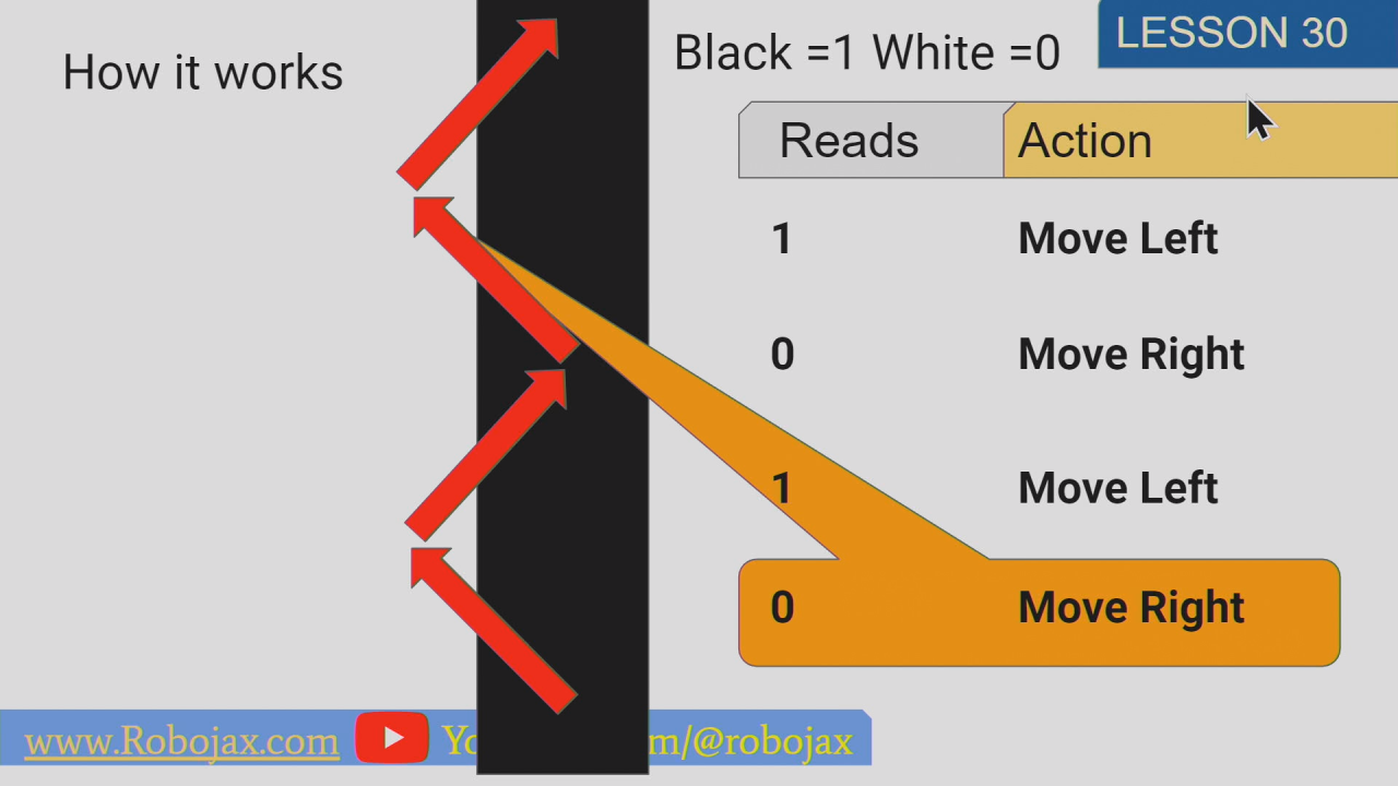
int speed = 150;//0 to 255The logic is simple: if the sensor reads HIGH (black line), the car turns left; otherwise, it turns right. The custom functions moveLeft() and moveRight() control the motors to achieve this. For example, to turn left, the right motor spins while the left motor stops, pivoting the car. This behavior is explained in detail in the video (in video at 10:39).
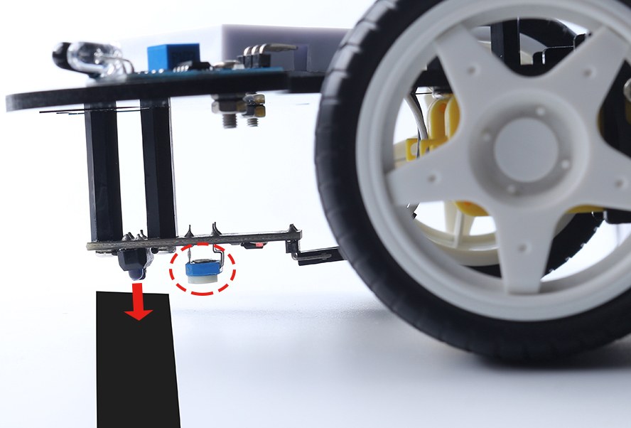
Positioning the line tracker on black line. Also adjusting the sensitivity.
Live Project Demonstration
The video concludes with a live demonstration of the line-following car (in video at 13:13). The car is placed on a black track, and the sensor is positioned directly over the line. As the car moves, the sensor detects the black line and the white background, sending signals to the motors to adjust its direction. The demonstration shows the car successfully completing a full circle, proving the effectiveness of the simple left/right correction logic.
Chapters
- [00:00] Introduction to Line Tracking
- [01:09] How the Line Tracking Module Works
- [04:04] Wiring the Line Tracking Module
- [04:23] Testing the Sensor with the Serial Monitor
- [07:27] Understanding the Line-Following Logic
- [09:08] Code for the Line-Following Car
- [11:37] Demonstration of the Line-Following Car
- [13:13] Live Test on a Black Track
Bilder
This code has not been parsed yet. Please return to the admin panel to parse it.Common Course Links
Common Course Files
Resurser och referenser
Inga resurser än.
Filer📁
Inga filer tillgängliga.





![[ZYAS]5957 Adafruit DVI Sock For Pico Adapter Accessories - Works With Hdmi Displays Graphics Output Interface](https://ae-pic-a1.aliexpress-media.com/kf/S8ba765e7fd1d4b4591ab9d0793e4e9ebg.jpg)