โค้ด Arduino และวิดีโอสำหรับโมดูลเซนเซอร์แสงพร้อมรีเลย์
ในบทช่วยสอนนี้ เราจะเรียนรู้วิธีการใช้โมดูลเซนเซอร์แสงเพื่อควบคุมหลอดไฟ AC โปรเจกต์นี้จะทำให้หลอดไฟเปิดโดยอัตโนมัติเมื่อมืดและปิดเมื่อสว่าง ซึ่งมีประโยชน์อย่างยิ่งสำหรับการใช้งาน เช่น ไฟภายนอกอาคารหรือไฟในโรงรถ เมื่อจบบทช่วยสอนนี้ คุณจะได้ระบบที่ทำงานได้ซึ่งสามารถจัดการแสงได้อย่างมีประสิทธิภาพตามสภาพแวดล้อม (ในวิดีโอที่ 02:15)
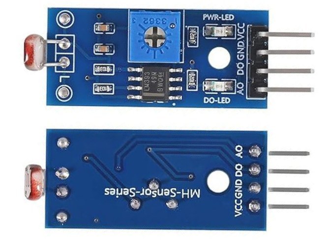
เราจะใช้โมดูลเซนเซอร์แสง ซึ่งประกอบด้วยตัวต้านทานไวแสง (LDR) สำหรับตรวจจับระดับแสง และรีเลย์สำหรับควบคุมหลอดไฟ AC ระบบจะรวมโพเทนชิโอมิเตอร์เพื่อปรับความไวของการตรวจจับแสงด้วย การตั้งค่านี้ช่วยให้สามารถควบคุมแสงได้ทั้งแบบดิจิทัลและแอนะล็อกตามแสงโดยรอบที่เซนเซอร์ตรวจจับได้ สำหรับคำอธิบายโดยละเอียด โปรดดูวิดีโอที่ 04:30
อธิบายฮาร์ดแวร์
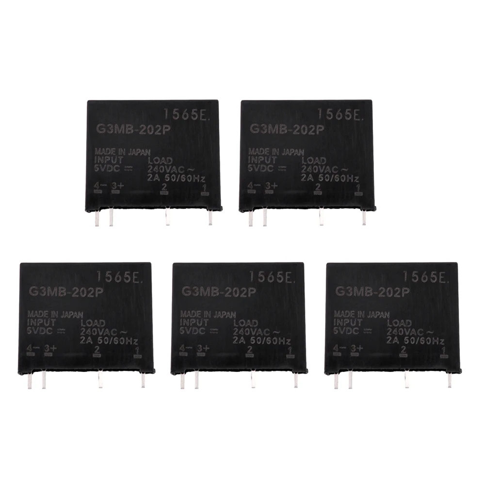
ส่วนประกอบหลักของการประกอบนี้คือโมดูลเซนเซอร์แสง รีเลย์ และ Arduino โมดูลเซนเซอร์แสงประกอบด้วย LDR ที่เปลี่ยนความต้านทานตามความเข้มของแสง โดยให้เอาต์พุตแบบดิจิทัลหรือแอนะล็อก รีเลย์ทำหน้าที่เป็นสวิตช์ที่สามารถควบคุมหลอดไฟ AC แรงดันสูงได้ในขณะที่ทำงานอย่างปลอดภัยด้วย Arduino แรงดันต่ำ การแยกส่วนนี้มีความสำคัญต่อความปลอดภัยและการทำงาน
รีเลย์มีขาหลักสามขา: คอมมอน (COM) ปกติเปิด (NO) และปกติปิด (NC) เมื่อถูกกระตุ้น รีเลย์จะเชื่อมต่อขาคอมมอนกับขาปกติเปิด ทำให้กระแสไหลผ่านหลอดไฟที่เชื่อมต่ออยู่ กลไกนี้ทำให้รีเลย์สามารถควบคุมหลอดไฟตามสัญญาณที่ได้รับจาก Arduino
รายละเอียดดาต้าชีต
| ผู้ผลิต | ทั่วไป |
|---|---|
| หมายเลขชิ้นส่วน | โมดูลเซนเซอร์แสง |
| แรงดันไฟฟ้าลอจิก/IO | 5 โวลต์ |
| แรงดันไฟฟ้าจ่าย | 5 โวลต์ |
| กระแสเอาต์พุต (ต่อช่อง) | 10 มิลลิแอมป์ |
| กระแสสูงสุด (ต่อช่อง) | 20 มิลลิแอมป์ |
| คำแนะนำความถี่ PWM | ไม่มี |
| เกณฑ์ลอจิกอินพุต | 2.5 โวลต์ (สูง) / 0.8 โวลต์ (ต่ำ) |
| แรงดันตก / RDS(on) / ความอิ่มตัว | 0.2 โวลต์โดยทั่วไป |
| ขีดจำกัดความร้อน | 85 องศาเซลเซียส |
| แพ็คเกจ | โมดูล |
| หมายเหตุ / รุ่นต่างๆ | รวมโพเทนชิโอมิเตอร์สำหรับปรับความไว |
- ตรวจสอบให้แน่ใจว่ามีการระบายความร้อนที่เหมาะสมสำหรับรีเลย์
- ใช้ตัวต้านทานพุลอัพสำหรับอินพุตเซนเซอร์แสง
- ตรวจสอบพิกัดแรงดันไฟฟ้าก่อนเชื่อมต่ออุปกรณ์ AC
- หลีกเลี่ยงการสัมผัสสายไฟที่เปิดอยู่เมื่อระบบได้รับพลังงาน
- ปรับโพเทนชิโอมิเตอร์เพื่อความไวแสงที่ต้องการ
คำแนะนำการเดินสายไฟ

ในการเดินสายไฟโมดูลเซนเซอร์แสงและรีเลย์เข้ากับ Arduino ให้เริ่มต้นโดยเชื่อมต่อขา VCC ของโมดูลเซนเซอร์แสงเข้ากับขา 5V บน Arduino จากนั้นเชื่อมต่อขากราวด์ของเซนเซอร์แสงเข้ากับขา GND บน Arduino ขาเอาต์พุตดิจิทัลของเซนเซอร์แสงควรเชื่อมต่อกับขา 2 บน Arduino ในขณะที่ขาเอาต์พุตแอนะล็อกเชื่อมต่อกับ A0 สำหรับการอ่านค่าแบบแอนะล็อก
ตอนนี้ สำหรับรีเลย์ ให้เชื่อมต่อขา VCC เข้ากับขา 5V บน Arduino และขากราวด์เข้ากับ GND ขาอินพุตของรีเลย์ควรเชื่อมต่อกับขา 9 บน Arduino สุดท้าย เชื่อมต่อสายหนึ่งของหลอดไฟ AC เข้ากับขาคอมมอน (COM) ของรีเลย์และสายอีกเส้นเข้ากับขาปกติเปิด (NO) การตั้งค่านี้จะทำให้รีเลย์สามารถควบคุมหลอดไฟ AC ตามการอ่านค่าจากเซนเซอร์แสง

ตัวอย่างโค้ดและคำอธิบาย
ในโค้ดดิจิทัลพื้นฐานสำหรับเซนเซอร์แสง เรากำหนดขาสำหรับเซนเซอร์และรีเลย์ ฟังก์ชัน setup เริ่มต้นการสื่อสารซีเรียลและตั้งค่าโหมดขา:
#define LIGHT 2 // กำหนดขา 2 สำหรับเซนเซอร์
#define RELAY 9 // กำหนดขา 9 สำหรับรีเลย์

void setup() {
  Serial.begin(9600); // ตั้งค่ามอนิเตอร์ซีเรียล
  pinMode(LIGHT, INPUT_PULLUP); // กำหนดขาเป็นอินพุตเซนเซอร์
  pinMode(RELAY, OUTPUT); // กำหนดขาเป็นเอาต์พุตสำหรับรีเลย์
}
โค้ดนี้ตั้งค่าขา 2 เป็นอินพุตสำหรับอ่านเซนเซอร์แสงและขา 9 เป็นเอาต์พุตเพื่อควบคุมรีเลย์ มอนิเตอร์ซีเรียลยังถูกเริ่มต้นเพื่อให้ข้อเสนอแนะเกี่ยวกับสถานะแสง
ภายในฟังก์ชัน loop เราอ่านสถานะเซนเซอร์อย่างต่อเนื่อง:
int L = digitalRead(LIGHT); // อ่านเซนเซอร์
if (L == 1) {
  Serial.println(" เปิดไฟ");
  digitalWrite(RELAY, LOW); // เปิดรีเลย์
} else {
  Serial.println("  === ปิดไฟ");
  digitalWrite(RELAY, HIGH); // ปิดรีเลย์
}
ตรรกะนี้ตรวจสอบสถานะของเซนเซอร์แสงและเปิดหรือปิดรีเลย์ตามนั้น พร้อมให้ข้อเสนอแนะผ่านมอนิเตอร์ซีเรียล
ในโค้ดแอนะล็อกขั้นสูง เรารวมวิธีการอ่านค่าจากเอาต์พุตแอนะล็อก:
if (digital == true) {
  int L = digitalRead(LIGHT); // อ่านเซนเซอร์
  if (L == 1) {
    Serial.println(" เปิดไฟ");
    digitalWrite(RELAY, LOW); // เปิดรีเลย์
  } else {
    Serial.println("  === ปิดไฟ");
    digitalWrite(RELAY, HIGH); // ปิดรีเลย์
  }
} else {
  int a0Value = analogRead(A0); // อ่านค่า A0
  if (a0Value >= LightValue) {
    Serial.print(analogRead(A0));
    Serial.println(" เปิดไฟ");
    digitalWrite(RELAY, LOW); // เปิดรีเลย์
  } else {
    Serial.print(analogRead(A0));
    Serial.println("  === ปิดไฟ");
    digitalWrite(RELAY, HIGH); // ปิดรีเลย์
  }
}
ส่วนนี้ช่วยให้ปรับความไวตามค่าการอ่านแบบแอนะล็อกจากเซนเซอร์แสง ให้การควบคุมเกณฑ์การเปิดไฟมีความแม่นยำมากขึ้น
การสาธิต / สิ่งที่คาดหวัง
เมื่อตั้งค่าสำเร็จและเปิดเครื่อง ไฟควรเปิดในสภาพแสงน้อยและปิดในสภาพแสงจ้า คุณสามารถทดสอบระบบได้โดยการปิดเซนเซอร์แสงเพื่อจำลองความมืดและสังเกตการทำงานของรีเลย์ หากตั้งค่าอย่างถูกต้อง จอแสดงผลแบบอนุกรมจะแสดง "light is ON" หรือ "light is OFF" ตามค่าที่เซนเซอร์อ่านได้ ควรระมัดระวังการกลับขั้วเมื่อเชื่อมต่อไฟ AC เนื่องจากอาจทำให้เกิดการทำงานผิดปกติหรืออันตรายต่อความปลอดภัย (ในวิดีโอที่เวลา 10:00)
ไทม์สแตมป์ในวิดีโอ
- 00:00 แนะนำโปรเจกต์
- 02:15 ภาพรวมของชิ้นส่วนและการเดินสายไฟ
- 04:30 คำอธิบายโค้ด
- 10:00 การสาธิตการทำงาน
ภาพ


++
/*
 * This is the Arduino code for the Light module for Arduino (basic).
This video shows you how to turn an AC light ON during the night using a light sensor
and turn it OFF during the day. This code is a basic version where
the digital output of the module is used.
 // Written for Robojax.com video

 * Watch the HC-SR505 Motion Sensor video for details https://youtu.be/qhThpxiXubI
 * Code is available at http://robojax.com/learn/arduino

 *
 // Written by Ahmad S. for Robojax.com on
// February 10, 2018 at 13:43 in Ajax, Ontario, Canada
*/
#define LIGHT 2 // define pin 2 for sensor
#define RELAY 9 // define pin 9 as for relay

/*
 * Permission granted to share this code given that this
 * note is kept with the code.
 * Disclaimer: this code is "AS IS" and for educational purposes only.
 *
 */

void setup() {
  // Light LDR Sensor Code by Robojax.com 20180210
  Serial.begin(9600);// setup Serial Monitor to display information
  pinMode(LIGHT, INPUT_PULLUP);// define pin as Input  sensor
  pinMode(RELAY, OUTPUT);// define pin as OUTPUT for relay
}

void loop() {
  // Light LDR Sensor Code by Robojax.com 20180210
  int L =digitalRead(LIGHT);// read the sensor

      if(L == 1){
    Serial.println(" light is ON");
    digitalWrite(RELAY,LOW);// turn the relay ON
  }else{

     Serial.println("  === light is OFF");
     digitalWrite(RELAY,HIGH);// turn the relay OFF
  }
  delay(500);
 // Light LDR Sensor Code by Robojax.com 20180210
}/*
Light Sensor module for Arduino (Advanced: analog)
This video shows you how to turn an AC light ON during the night using
a light sensor and turn it OFF during the day.
This code is to control a light either digitally and control
the sensitivity with the potentiometer on the module.
You can control the light using an analog value from pin A0
and set your own sensitivity. Make sure you turn the
potentiometer to the maximum value and set digital=false.
// Written for Robojax.com video
* Watch Light Sensor video https://youtu.be/CyDAWcY8_5w
* Code is available at http://robojax.com/learn/arduino
*
*/
#define LIGHT 2 // define pin 2 for sensor
#define RELAY 9 // define pin 9 as for relay
/*
*
// Written by Ahmad S. for Robojax.com on
// February 10, 2018 at 13:43 in Ajax, Ontario, Canada
* Permission granted to share this code given that this
* note is kept with the code.
* Disclaimer: this code is "AS IS" and for educational purposes only.
*
*/
// LDR, Light Dependant Resistor
boolean digital = false;// set true to use digital and control the sensitivity with potentiometer on the module
// set to false to control with A0 value on Arduino
unsigned int LightValue = 350;// LightValue to determine
// at what value the relay should be ON
void setup() {
// Light LDR Sensor Code by Robojax.com 20180210
Serial.begin(9600);// setup Serial Monitor to display information
pinMode(LIGHT, INPUT_PULLUP);// define pin as Input sensor
pinMode(RELAY, OUTPUT);// define pin as OUTPUT for relay
}
void loop() {
delay(500);
relay();// call the relay() method
// Light LDR Sensor Code by Robojax.com 20180210
}
void relay()
{
if(digital == true)
{
// Light LDR Sensor Code by Robojax.com 20180210
int L =digitalRead(LIGHT);// read the sensor
if(L == 1){
Serial.println(" light is ON");
digitalWrite(RELAY,LOW);// turn the relay ON
}else{
Serial.println(" === light is OFF");
digitalWrite(RELAY,HIGH);// turn the relay OFF
} // if
}// if digital end
else
{
int a0Value = analogRead(A0);// read A0 value
if( a0Value >= LightValue){
Serial.print(analogRead(A0));
Serial.println(" Light is ON");
digitalWrite(RELAY,LOW);// turn the relay ON
}else{
Serial.print(analogRead(A0));
Serial.println(" === light OFF");
digitalWrite(RELAY,HIGH);// turn the relay OFF
} // if
}
}สิ่งที่คุณอาจต้องการ
-
อเมซอน
แหล่งข้อมูลและเอกสารอ้างอิง
ยังไม่มีทรัพยากรเลย
ไฟล์📁
ไฟล์ Fritzing
-
LDR light sensor module black
LDR_module_black.fzpz0.01 MB