Lesson 17/31: How to interrupt a delay in Arduino and Light Dependant Resistor LDR | Robojax
In this guide, we'll explore two essential Arduino concepts: interrupts and light-dependent resistors (LDRs). You'll learn how to interrupt delays in your code so your Arduino can respond instantly to button presses, and then we'll build a light-sensing circuit that can automatically turn on a buzzer or light at night. This project is perfect for anyone looking to move beyond basic blinking LED sketches and start building responsive, real-world automation projects. You can apply these skills to create a smart night light for your hallway, a simple security alarm that sounds when a door opens, a solar-powered garden light that activates at dusk, or an automatic curtain that closes when the sun goes down. The lesson is based on the SunFounder 3-in-1 Arduino kit, but the concepts apply to any standard Arduino board.

Hardware & Components
To follow along with this project, you will need the following components. A standard Arduino Uno or Nano is perfect for this build.
- Arduino Uno or Nano
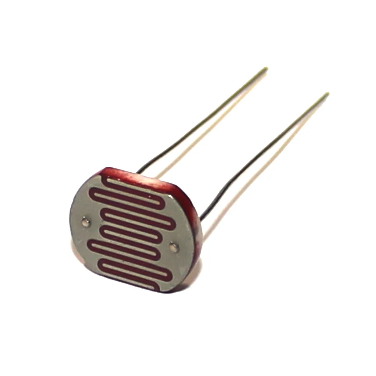
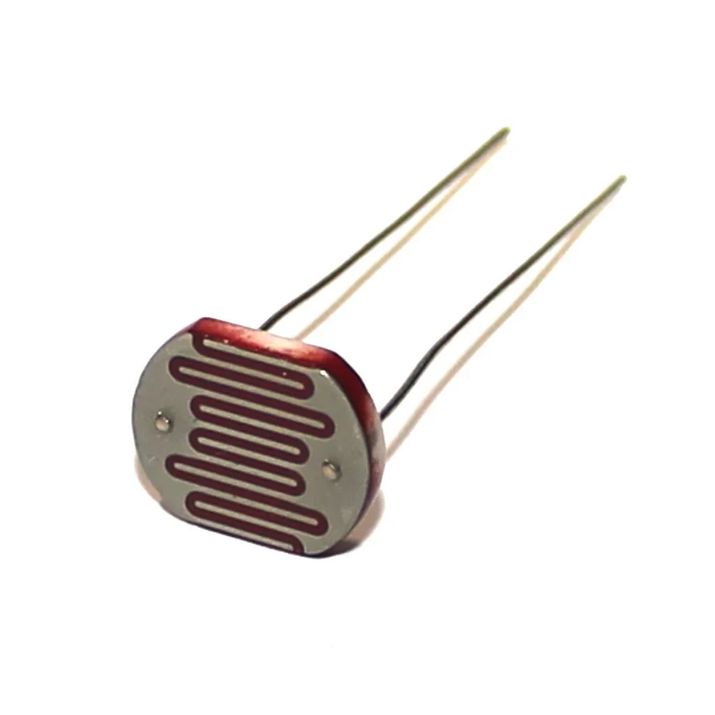
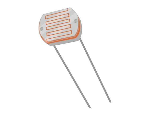
- Light Dependent Resistor (LDR), such as the Kweeds KM601
- 10k Ohm Resistor
- Push Button
- Buzzer
- Breadboard and Jumper Wires
Understanding Arduino Interrupts
In a standard Arduino sketch, the loop() function runs continuously, executing tasks line by line. When you use a delay(), the Arduino stops doing anything else for that duration. This is a problem if you need to respond to an important event, like a button press, while another task is running. For example, if you have a one-second delay to blink an LED, a button press might not be registered for up to a second, which feels unresponsive (in video at 08:13).
Arduino interrupts solve this problem. An interrupt is a hardware feature that allows a specific pin to "interrupt" the main program, pause whatever it's doing, and run a special function called an Interrupt Service Routine (ISR). This allows your Arduino to respond to high-priority events instantly, regardless of what else is happening. It's important to note that not all pins support interrupts. On the Arduino Uno and Nano, only pins 2 and 3 can be used for this purpose (in video at 02:37). Other boards like the Mega have more options, but for this project, we'll stick with pin 2.
Interrupts can be triggered by different state changes on the pin: LOW, CHANGE, RISING, and FALLING. The CHANGE mode triggers the interrupt whenever the pin's state changes from HIGH to LOW or LOW to HIGH, which is perfect for a button press toggle.
Wiring Guide
We'll be building two circuits in this lesson. The first demonstrates interrupts with a button and buzzer, and the second uses an LDR to sense light levels. Let's start with the interrupt circuit.
Circuit 1: Button and Buzzer for Interrupt Demo
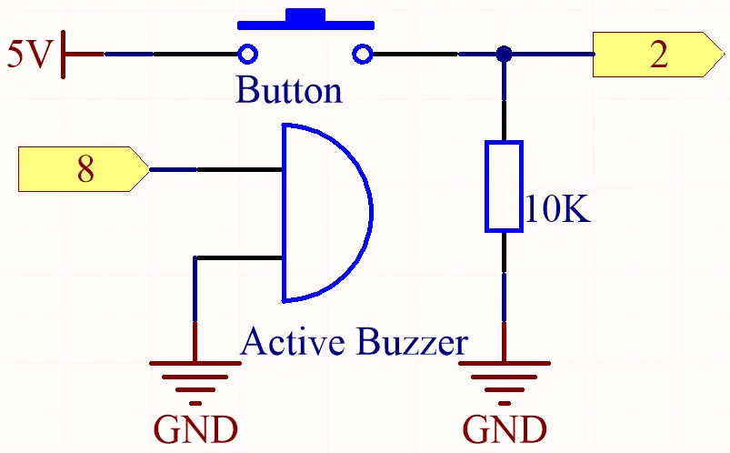
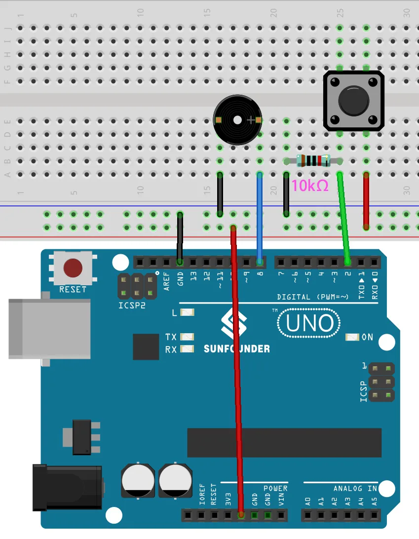
This circuit is straightforward. The button is connected to pin 2, which is our interrupt pin. A 10k Ohm pull-down resistor ensures the pin reads LOW when the button is not pressed, and HIGH when it is. The buzzer is connected to pin 8.
For the interrupt demo, connect the components as follows:
- Push Button: Connect one leg to 5V and the other leg to digital pin 2. Connect a 10k Ohm resistor from pin 2 to GND.
- Buzzer: Connect the negative lead to GND and the positive lead to digital pin 8.
Circuit 2: LDR and Buzzer for Light Sensing
For the LDR circuit, we use a voltage divider configuration. The LDR's resistance changes with light, which alters the voltage at the analog pin. When it's dark, the LDR has a high resistance (around 10k Ohms), and when it's bright, the resistance drops significantly (in video at 16:25). This change in resistance is what we measure.
A voltage divider is necessary because the Arduino can only read voltage, not resistance. By placing the LDR in series with a fixed 10k Ohm resistor, the voltage at the point between them changes proportionally to the LDR's resistance. This voltage is then read by the Arduino's analog-to-digital converter (ADC).
For the LDR demo, connect the components as follows:
- LDR: Connect one leg to 5V and the other leg to analog pin A0.
- 10k Ohm Resistor: Connect from the LDR leg that goes to A0 down to GND. This creates the voltage divider.
- Buzzer: Connect the negative lead to GND and the positive lead to digital pin 8.
Note: The exact pin assignments are defined in the code and can be changed to suit your setup.
Code Explanation
We will focus on the user-configurable parts of the provided code that control the project's behavior. The full program is available for download below the article.
The code is designed to be easily modified. At the top of the sketch, you'll find the key variables that you can adjust.
const byte buzzerPin = 8;
const byte interruptPin = 2;
volatile byte state = LOW;
int count=0;
Here, buzzerPin is set to pin 8, which is where you connect the buzzer. The interruptPin is set to pin 2, which is the pin that will listen for the button press. The state variable is a volatile byte that holds the current state of the buzzer (HIGH or LOW). It is marked volatile because it is modified inside the interrupt service routine (ISR), and this keyword ensures the Arduino always reads the latest value. The count variable is a simple counter that increments in the main loop to demonstrate that the loop is still running while the interrupt is active.
In the setup() function, the buzzer pin is set as an OUTPUT, and the interrupt pin is set as an INPUT. The critical line is attachInterrupt(), which is where you configure the interrupt. This function tells the Arduino which pin to watch, which function to call when the interrupt occurs, and what trigger condition to use.
attachInterrupt(digitalPinToInterrupt(interruptPin), noisy, CHANGE);This line attaches an interrupt to the specified pin. The digitalPinToInterrupt() function converts the pin number to the correct interrupt number. The noisy is the name of the function that will be called when the interrupt is triggered. Finally, CHANGE is the mode, which triggers the interrupt on any state change of the pin. You can change this to RISING, FALLING, or LOW depending on your needs.
The noisy() function is the ISR. It is a simple toggle function that flips the state of the buzzer. When the button is pressed, the interrupt triggers this function, which inverts the state variable and writes it to the buzzer pin. This allows you to turn the buzzer on and off with each button press, even while the main loop is busy counting and delaying.
To change the project's behavior to activate the buzzer at night instead of during the day, you would modify the conditional logic in the main loop, swapping the digitalWrite() commands for the HIGH and LOW states.
Live Project & Demonstration
In the demonstration, you'll see two key experiments. First, the interrupt circuit is shown running without the interrupt code, where the delay in the loop makes the button response sluggish. This highlights the problem that interrupts solve.
Then, with the interrupt code loaded, the serial monitor shows the counter incrementing every second. When the button is pressed, the buzzer toggles on or off instantly, regardless of the delay in the main loop. This proves that the interrupt successfully bypasses the waiting time and executes its task immediately (in video at 14:07).
For the LDR part, the serial monitor prints the raw analog value. You can see the value is high (around 960) in bright light and drops significantly (to around 400 or lower) when the sensor is covered. This demonstrates how the LDR's resistance changes with light intensity. The code then uses a threshold value to determine if it is "day" or "night" and controls the buzzer accordingly. By covering the sensor to simulate night, you can trigger the buzzer, and by exposing it to light, you can turn it off.
Chapters
- [00:00] Introduction to Arduino Interrupts and LDR
- [01:43] The Problem with Delays in Arduino Code
- [03:37] Understanding Interrupt Pins and Modes
- [04:20] Wiring the Button and Buzzer Circuit
- [06:22] Code Explanation for the Delay Demo
- [07:48] Demonstration of the Delay Problem
- [09:26] Implementing and Coding the Interrupt
- [11:50] How the Interrupt Function Works
- [14:26] Introduction to Light Dependent Resistors (LDR)
- [15:44] Measuring LDR Resistance with a Multimeter
- [17:22] Wiring the LDR and Buzzer Circuit
- [19:55] Code for Reading LDR Values
- [20:49] Demonstration of LDR Value Changes
- [22:08] Setting Day and Night Thresholds
- [23:40] Code to Control a Buzzer with LDR
- [25:21] Demonstration of Automatic Night Light
Images
/*
Lesson 20/31: interrupt a delay in Arduino and Light Dependent Resistor LDR
Get this code and watch video Download and resource page https://robojax.com/RJT600
YouTube video https://www.youtube.com/watch?v=N_L11m1v_yk


 * This code is "AS IS" without warranty or liability. Free to be used as long as you keep this note intact.*
 * This code has been download from Robojax.com
    This program is free software: you can redistribute it and/or modify
    it under the terms of the GNU General Public License as published by
    the Free Software Foundation, either version 3 of the License, or
    (at your option) any later version.

    This program is distributed in the hope that it will be useful,
    but WITHOUT ANY WARRANTY; without even the implied warranty of
    MERCHANTABILITY or FITNESS FOR A PARTICULAR PURPOSE.  See the
    GNU General Public License for more details.

    You should have received a copy of the GNU General Public License
    along with this program.  If not, see <https://www.gnu.org/licenses/>.
 */
const byte buzzerPin = 8;
const byte interruptPin = 2;
volatile byte state = LOW;
int count=0;

void setup() {
  pinMode(buzzerPin, OUTPUT);
  pinMode(interruptPin, INPUT);
  attachInterrupt(digitalPinToInterrupt(interruptPin), noisy, CHANGE);
  Serial.begin(9600);
  digitalWrite(buzzerPin, state);
}

void loop() {
  count++;
  Serial.println(count);
  delay(1000);
}

void noisy() {
  state = !state;
  digitalWrite(buzzerPin, state);
}
Common Course Links
Common Course Files
Things you might need
-
AmazonSunFounder Arduino Learning Kit on AliExpresss.click.aliexpress.com
-
Amazon
-
Amazon
-
Amazon
-
Amazon
Resources & references
-
DocumentationDocumentation for SunFounder 3 in 1 IoT/Smart Car/Learning Kitdocs.sunfounder.com
-
ExternalPurchase SunFounder's 3-in-1 Smart car learning kitsunfounder.com
Files📁
Arduino Libraries (zip)
-
SunFounder's 3-in-1 Smart Car learning kit source code
3in1-kit-main-v2.zip12.80 MB