Lesson 3/31: Project LED Blink, What is Breadboard, LED and Resistor Using SunFounder Kit
In this lesson, we will explore the fundamental concepts of using an Arduino board, focusing on the LED Blink project. This project will help you understand how to wire components like an LED and a resistor on a breadboard, and how to write the corresponding code to make the LED blink. By the end of this tutorial, you will have a practical understanding of basic electronics and programming with Arduino.
The LED Blink project is a great starting point for beginners. It involves connecting an LED and a resistor to an Arduino board and writing a simple program to control the LED's blinking pattern. This exercise not only teaches you about coding structure but also about the components used in electronics, such as LEDs and resistors. For further clarification, please refer to the video (in video at 00:00).
Resistor and LED Explained

In this project, you will need a few key components: an Arduino Uno board, a breadboard, an LED, and a resistor (220 Ohm). The Arduino board serves as the brain of the project, executing the code that controls the LED. The breadboard is used for prototyping the circuit without soldering, allowing you to easily connect and disconnect components.

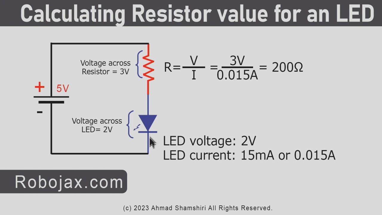
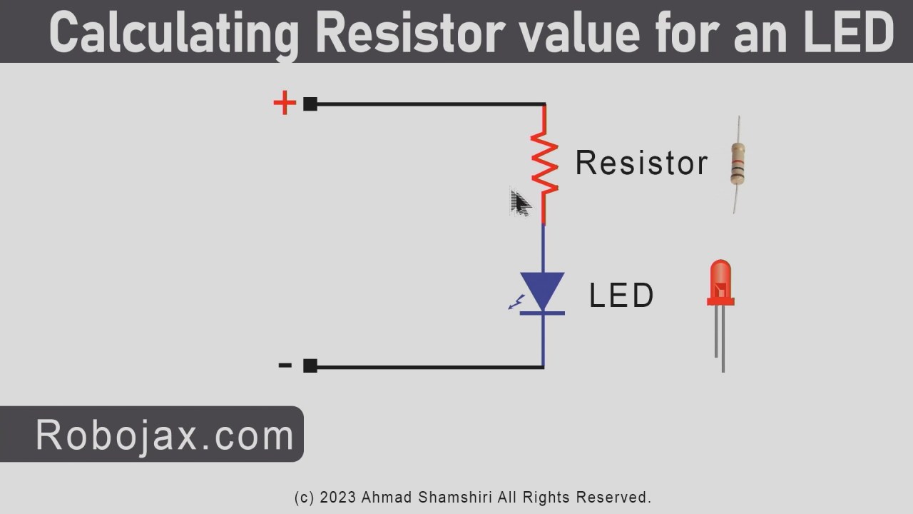
The LED (Light Emitting Diode) is a semiconductor device that emits light when current flows through it. The resistor is a passive component that limits the current flowing through the LED to prevent it from burning out. In this project, the LED will require about 2 volts to operate, and the resistor helps to manage the voltage from the Arduino’s 5 volts supply.
Datasheet Details
| Manufacturer | SunFounder |
|---|---|
| Part number | 220 Ohm Resistor |
| Power rating | 0.25 W |
| Tolerance | 5% |
| Color code | Red, Red, Brown |
- Use a resistor of 220 Ohm to limit current for the LED.
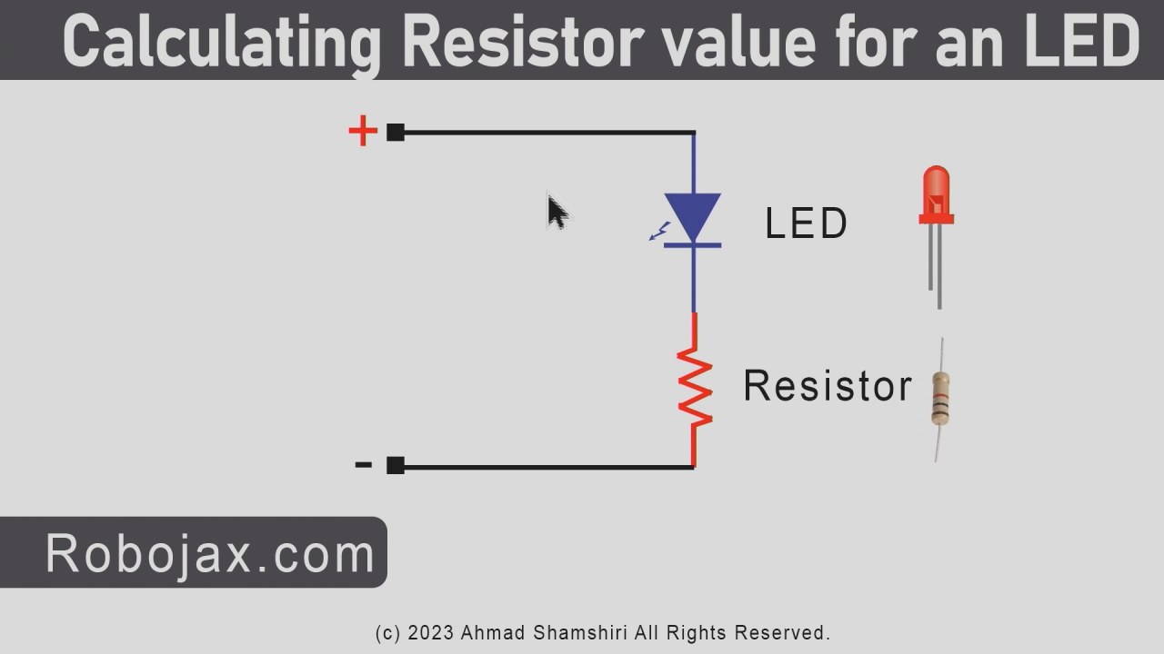
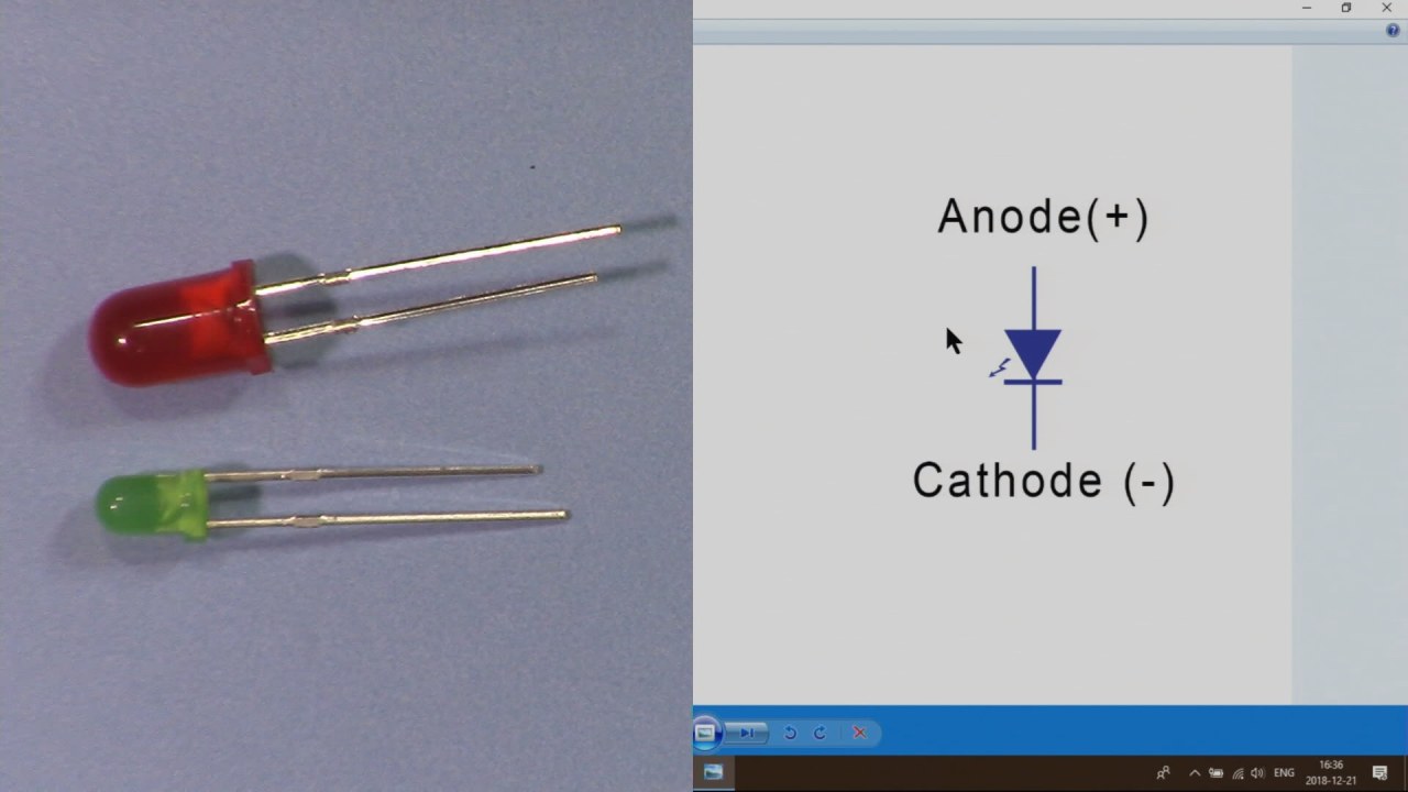
- Connect the anode (long pin) of the LED to the positive side of the circuit.
- The cathode (short pin) should be connected to the ground.
- Ensure correct polarity when connecting the LED.
- Double-check connections on the breadboard before powering the circuit.
Wiring Instructions

To wire the LED Blink project, start by placing the LED on the breadboard. Insert the longer pin (anode) into one of the rows on the breadboard. Next, connect a 220 Ohm resistor to the same row where the anode is connected. The other end of the resistor should go to a free row on the breadboard. This will connect to pin 9 on the Arduino.
Now, take a wire and connect it from the free row where the resistor is connected to pin 9 on the Arduino board. For the cathode (shorter pin) of the LED, connect it to the ground rail on the breadboard, which is also connected to the GND pin on the Arduino. Ensure that the ground connections are secure to avoid any issues when the circuit is powered.
Code Examples & Walkthrough
Let’s look at the structure of the code for the LED Blink project. The program consists of two main functions: setup() and loop(). The setup() function runs once when the Arduino is powered on or reset, and it initializes the LED pin.
void setup() {
  pinMode(LED_BUILTIN, OUTPUT);
}
In the setup() function, we use pinMode(LED_BUILTIN, OUTPUT) to set the built-in LED pin as an output. This allows the Arduino to control the LED by sending a high or low signal.
Next, the loop() function runs continuously, turning the LED on and off with a delay.
void loop() {
  digitalWrite(LED_BUILTIN, HIGH);  // turn the LED on
  delay(1000);                      // wait for a second
  digitalWrite(LED_BUILTIN, LOW);   // turn the LED off
  delay(1000);                      // wait for a second
}
In this excerpt, digitalWrite(LED_BUILTIN, HIGH) sends a high signal to the LED, turning it on. The program then waits for 1000 milliseconds (1 second) before turning the LED off with digitalWrite(LED_BUILTIN, LOW). This cycle repeats indefinitely, creating a blinking effect.
Demonstration / What to Expect
Once you have wired the components and uploaded the code to the Arduino, you should see the LED blinking on and off at one-second intervals. If the LED does not light up, check your connections for proper polarity and ensure the resistor is connected correctly. If you experience rapid blinking, you can adjust the delay values in the code to change the blinking speed (in video at 10:00).
Video Timestamps
- 00:00 Introduction
- 1:33 Arduino Setup() and Loop()
- 4:44 Arduino UNO explained
- 7:09 What is a resistor?
- 15:52 What is an LED
- 17:57 Calculating resistor value for LED
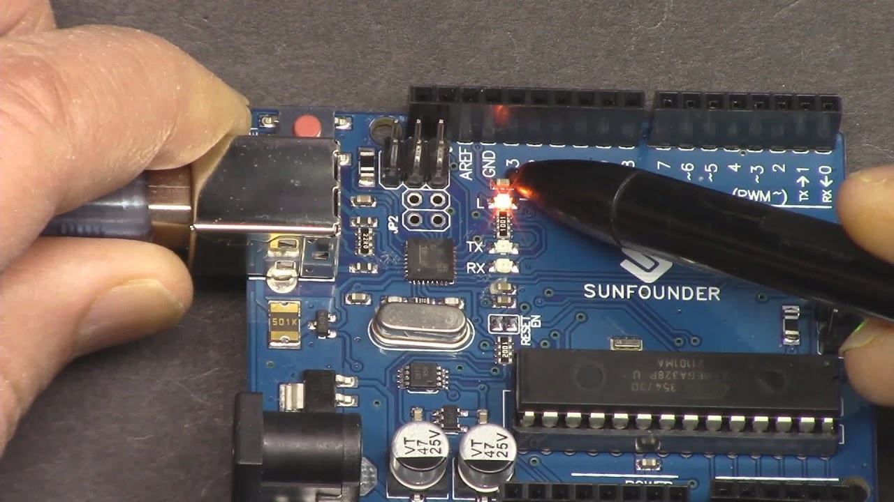
- 20:15 Built-in LED project
- 26:27 LED blink (Hello LED) project
图像
This code has not been parsed yet. Please return to the admin panel to parse it.Common Course Links
Common Course Files
资源与参考
尚无可用资源。
文件📁
没有可用的文件。