This tutorial is part of: Digital Relative Humidity & Temperature Sensor HTU21D
Videos related to Digital Relative Humidity & Temperature Sensor HTU21D. Links to other videos are below this article.

Lesson 35-2: Using the HTU21D Temperature Sensor Custom Code
In this tutorial, we will explore how to use the HTU21D temperature sensor with Arduino to measure temperature and humidity. The HTU21D is a reliable, low-power sensor that communicates over I2C, making it easy to integrate into your projects. By the end of this lesson, you will have a working custom code that reads temperature in Celsius, Fahrenheit, and Kelvin, as well as relative humidity.

Before we dive into the wiring and code, it's essential to understand the components involved. The HTU21D sensor requires minimal connections: power, ground, and two I2C wires for data transfer. This simplicity makes it an excellent choice for various applications, from weather stations to smart home devices. For a visual guide, refer to the video at timestamp 03:45.
Hardware Explained
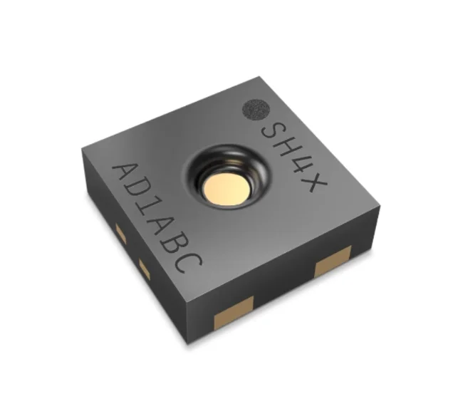
The primary component in this project is the HTU21D sensor, which measures temperature and humidity. This sensor can operate on voltages from 1.5V to 3.6V, making it versatile for different applications. It provides high-resolution readings, with temperature measurements ranging from -40°C to +125°C and humidity readings with a resolution of 0.04%.
Additionally, the sensor uses I2C communication, which requires two pins: SDA (data line) and SCL (clock line). This allows for easy integration with Arduino and other microcontrollers without the need for complex wiring. The Adafruit library simplifies interaction with the sensor, handling data retrieval and communication protocols seamlessly.
Datasheet Details
| Manufacturer | TE Connectivity |
|---|---|
| Part number | HTU21D-F |
| Logic/IO voltage | 1.5 – 3.6 V |
| Supply voltage | 3.3 V |
| Current consumption (idle) | 0.02 µA (typ.) |
| Current consumption (active) | 450 µA (typ.) |
| Temperature range | -40 to +125 °C |
| Humidity range | 0 to 100 %RH |
| Resolution | 0.04 %RH; 0.01 °C |
| Package | 6-pin DFN |
- Ensure correct power supply to avoid sensor damage.
- Use pull-up resistors on SDA and SCL lines if not integrated.
- Keep sensor connections short to minimize noise.
- Monitor the voltage during operation to maintain stability.
- Consider using a capacitor for decoupling near the power pins.
Wiring Instructions

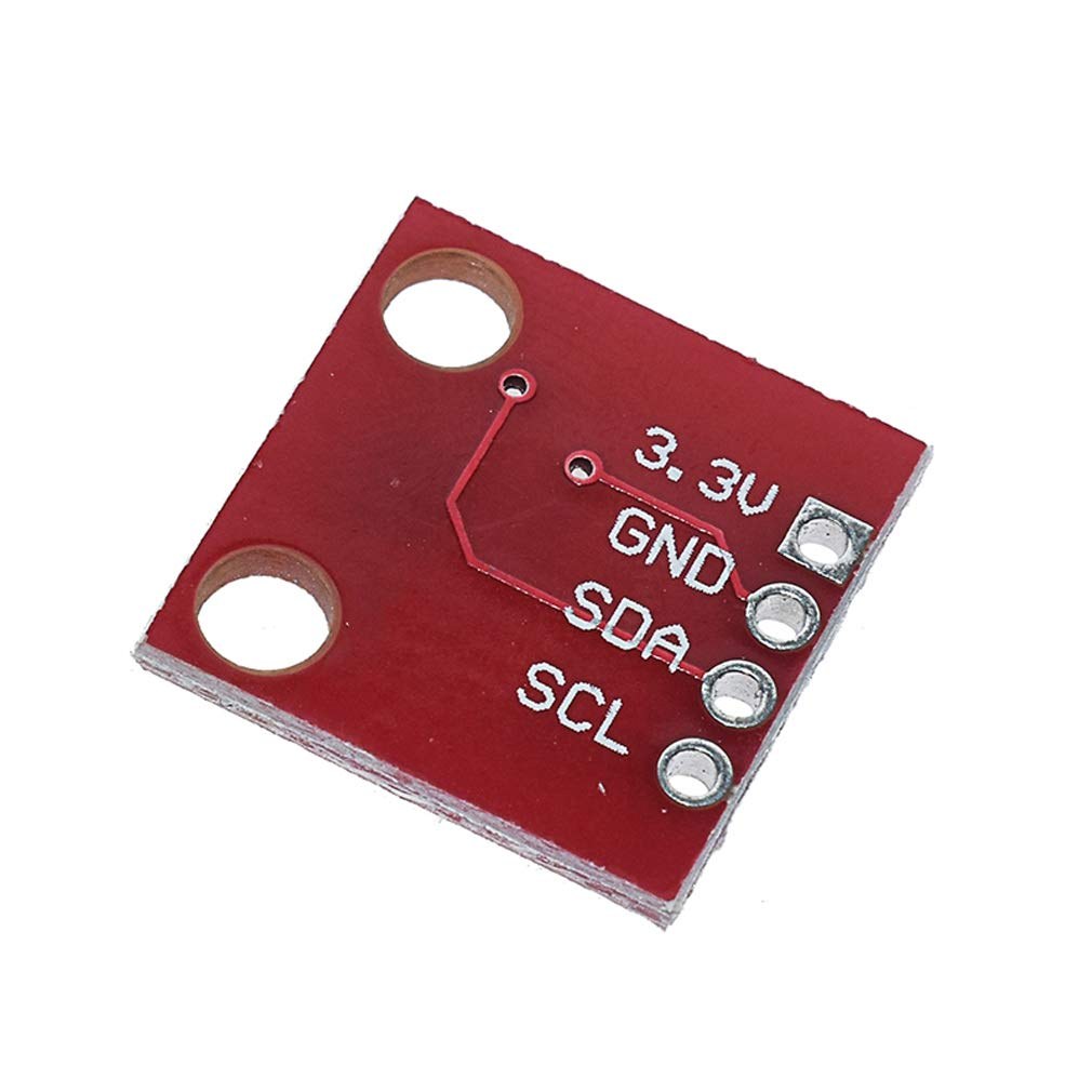
To wire the HTU21D temperature sensor, start by connecting the power and ground. Connect the left pin of the sensor to a 3.3V source, ensuring it can handle the required voltage. The second pin, typically marked in red, should go to ground.
Next, connect the SDA pin of the sensor to pin A4 on the Arduino, which serves as the data line for I2C communication. Then, connect the SCL pin to pin A5, which acts as the clock line. Make sure these connections are secure, as loose wires can lead to intermittent readings or failure to communicate with the sensor.
Code Examples & Walkthrough
In the code, we begin by including the necessary libraries and initializing the sensor. The line Adafruit_HTU21DF htu = Adafruit_HTU21DF(); creates an instance of the sensor class. In the setup() function, we start the serial communication and check if the sensor is connected properly.
void setup() {
  Serial.begin(9600);
  if (!htu.begin()) {
    Serial.println("Couldn't find sensor!");
    while (1);
  }
}
This snippet checks if the sensor is functioning correctly. If not, it prints an error message and halts the program. In the loop() function, we read the temperature and humidity values continuously.
void loop() {
    Serial.print(getHTU('C'));
    Serial.print("C");
    Serial.print(getHTU('H'));
    Serial.println("%");
    delay(1000);
}
Here, the function getHTU() is called with different parameters to retrieve temperature in Celsius and humidity. The delay ensures the readings are taken every second, giving a smooth output on the serial monitor. The full code is available for reference below the article.
Demonstration / What to Expect
Once everything is wired correctly and the code is uploaded, you should see temperature and humidity readings printed in the serial monitor. The temperature will be displayed in Celsius, followed by the corresponding humidity percentage. If you apply heat to the sensor, you should observe the temperature rise accordingly (in video at 10:15).
Be cautious of the sensor's limits; if the temperature exceeds 125°C, it may return an incorrect reading or display zero. Always ensure that your connections are secure and that the sensor is powered correctly to avoid any issues during operation.
Video Timestamps
- 00:00 Introduction
- 03:45 Wiring the Sensor
- 05:30 Code Walkthrough
- 10:15 Demonstration
- 12:00 Conclusion
Images
This tutorial is part of: Digital Relative Humidity & Temperature Sensor HTU21D
- Lesson 35-1: Using the HTU21D Temperature Sensor
- Lesson 35: Using HTU21D Temperature Sensor with Arduino
- Lesson 36: Using the HTU21D Temperature Sensor with an LCD Arduino Step-by-Step Course
- Using Two More HTU21DF Humidity and Temperature Sensors with Arduino
- Displaying Temperature from an HTU21D on an LCD
- Displaying Temperature from an HTU21D as a Bar Graph on an LCD
- How to Use the HTU21DF Humidity and Temperature Sensor with Arduino (Basic Code)
- How to Use the HTU21DF Humidity and Temperature Sensor with Arduino (Custom Code)
/*
 * Robojax Arduino Step-by-Step Course
 * Part 4: Temperature Sensors
 * Lesson 35: HTU21D Temperature Sensor Custom code

 * Written/Updated by Ahmad Shamshiri on July 13, 2019
 * in Ajax, Ontario, Canada


  Please watch video instructions here https://youtu.be/LyA0yAKlf9E
 This code is available at http://robojax.com/course1/?vid=lecture35

with over 100 lectures free on YouTube. Watch it here http://robojax.com/L/?id=338
Get the code for the course: http://robojax.com/L/?id=339
If you found this tutorial helpful, please support me so I can continue creating.
Make a donation using PayPal http://robojax.com/L/?id=64

 * Code is available at http://robojax.com/learn/arduino

 * This code is "AS IS" without warranty or liability. Free to be used as long as you keep this note intact.
 * This code has been downloaded from Robojax.com
    This program is free software: you can redistribute it and/or modify
    it under the terms of the GNU General Public License as published by
    the Free Software Foundation, either version 3 of the License, or
    (at your option) any later version.

    This program is distributed in the hope that it will be useful,
    but WITHOUT ANY WARRANTY; without even the implied warranty of
    MERCHANTABILITY or FITNESS FOR A PARTICULAR PURPOSE.  See the
    GNU General Public License for more details.

    You should have received a copy of the GNU General Public License
    along with this program.  If not, see <https://www.gnu.org/licenses/>.


 */
 /*


**************************************************
*
  This is an example for the HTU21D-F Humidity & Temperature Sensor

  Designed specifically to work with the HTU21D-F sensor from Adafruit
  ----> https://www.adafruit.com/products/1899

  These displays use I2C to communicate; 2 pins are required to
  interface
 ***************************************************
*/

#include <Wire.h>
#include "Adafruit_HTU21DF.h"

// Connect Vin to 3-5VDC
// Connect GND to ground
// Connect SCL to I2C clock pin (A5 on UNO)
// Connect SDA to I2C data pin (A4 on UNO)

Adafruit_HTU21DF htu = Adafruit_HTU21DF();

void setup() {
//Get the code for the course: http://robojax.com/L/?id=339
  Serial.begin(9600);
  Serial.println("Robojax.com");
  Serial.println("HTU21D-F test");

  if (!htu.begin()) {
    Serial.println("Couldn't find sensor!");
    while (1);
  }
}

void loop() {
//Get the code for the course: http://robojax.com/L/?id=339
    Serial.print(getHTU('C'));
    printDegree();
    Serial.println("C");

    Serial.print(getHTU('F'));
    printDegree();
    Serial.println("F");

    Serial.print(getHTU('K'));
    Serial.println("K");
    Serial.println(" ");

    Serial.print("Humidity:");
    Serial.print(getHTU('H'));
    Serial.println("%");

    if(getHTU('C') <81)
    {
      //digitalWrite(5, LOW);

    }
    delay(1000);
}


/*
 * @brief returns temperature or relative humidity
 * @param "type" is character
 *     C = Celsius
 *     K = Kelvin
 *     F = Fahrenheit
 *     H = Humidity
 * @return returns one of the values above
 * Usage: to get Fahrenheit type: getHTU('F')
 * to print it on serial monitor Serial.println(getHTU('F'));
 * Written by Ahmad Shamshiri on July 13, 2019
 * in Ajax, Ontario, Canada
 * www.Robojax.com
 */
float getHTU(char type)
{
	//Get the code for the course: http://robojax.com/L/?id=339
  float value;
    float temp = htu.readTemperature();
    float rel_hum = htu.readHumidity();
   if(type =='F')
   {
    value = temp *9/5 + 32;//convert to Fahrenheit
   }else if(type =='K')
   {
    value = temp + 273.15;//convert to Kelvin
   }else if(type =='H')
   {
    value = rel_hum;//return relative humidity
   }else{
    value = temp;// return Celsius
   }
   return value;
}//


/*
 * @brief prints degree symbol on serial monitor
 * @param none
 * @return returns nothing
 * Written by Ahmad Shamshiri on July 13, 2019
 * for Robojax Tutorial Robojax.com
 */
 void printDegree()
{
    Serial.print("\xC2");
    Serial.print("\xB0");
}
Things you might need
-
Amazon
-
eBayPurchase HTU21D from eBayebay.us
-
AliExpressPurchase HTU21D or SHT21 from AliExpresss.click.aliexpress.com
Resources & references
-
ExternalAdafruit HTU21D Library (GitHub)github.com
-
ExternalDifference between HTU21DF and HTU21D (image)robojax.com
-
External
-
ExternalHTU21D Datasheet (PDF)cdn-shop.adafruit.com
Files📁
Datasheet (pdf)
-
HTU21D_temerature_humidity_datasheet
HTU21D_temerature_humidity_datasheet.pdf0.96 MB