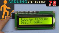
Lesson 91: Controlling a Servo Motor Using a Potentiometer and Displaying the Angle on an LCD
In this hands-on Arduino tutorial, you'll learn how to combine three essential components into one functional project: a servo motor, a potentiometer, and an I2C LCD display. By the end, you'll be able to turn a knob and watch a servo arm move in real-time while the exact angle is displayed on the screen. This project is perfect for building intuitive physical interfaces where you need both visual feedback and precise positioning.
This project bridges the gap between analog input and physical output. A potentiometer acts as your analog control dial, the servo motor translates that dial position into a physical angle (0 to 180 degrees), and the LCD screen provides immediate visual confirmation of the current angle. This setup is the foundation for countless practical applications:
- Building a robotic arm joint with a manual control knob for precise positioning
- Creating a pan-and-tilt camera mount where you control the direction with a dial
- Developing an analog gauge that displays values on a screen for a custom instrument panel
- Constructing a remote-controlled model vehicle's steering mechanism with visual feedback
Hardware Components
To build this project, you'll need the following components:
- Arduino board (Uno or similar)
- Servo motor (standard 5V hobby servo)
- Potentiometer (10kΩ recommended)
- I2C LCD display (16x2 or 20x4)
- Breadboard and jumper wires
Wiring Guide
This project cleverly uses two spare digital pins on the Arduino to supply 5V power to the potentiometer and LCD, avoiding the need for extra power rails on the breadboard. Pin 8 is configured as an output and set HIGH to power the potentiometer, while pin 4 does the same for the LCD's VCC. This technique is useful when you need additional 5V sources without adding more hardware.
The wiring connections are as follows (in video at 05:08):
- Servo: Signal wire to digital pin 3, power to 5V, ground to GND
- Potentiometer: Center pin to analog pin A0, one outer pin to pin 8 (VCC2), other outer pin to GND
- LCD: VCC to pin 4 (VCC3), GND to GND, SDA to A4, SCL to A5
Code Explanation
The code for this project builds on standard servo control by adding LCD display functionality. Let's focus on the key user-configurable elements you'll need to adjust for your specific setup.
Pin Definitions: The pins are defined at the top of the sketch and can be changed to match your wiring:
int potpin = A0;  // analog pin for potentiometer
int servoPin = 3; // digital PWM pin for servo (3, 5, 6, 9, 10, 11)
int VCC2 = 8;     // extra 5V pin for potentiometer
int VCC3 = 4;     // extra 5V pin for LCD
LCD Configuration: The I2C address is critical and must match your specific LCD module. Many modules use 0x27, but this code uses 0x3F. You may need to run an I2C scanner sketch to find your address:
LiquidCrystal_I2C lcd(0x3F, 16, 2); // address, columns, rows
Servo Resolution Adjustment: The analog reading is divided by 5 to reduce fluctuation. You can adjust this value to balance stability against resolution. A higher divisor (like 10) gives a perfectly stable reading but reduces the number of servo positions you can achieve:
val = analogRead(potpin)/5; // divide by 5 for stability
Degree Symbol Positioning: The code includes logic to position the degree symbol (°) correctly next to the angle value, whether it's a one, two, or three-digit number. This ensures the display always looks clean and professional.
Live Project Demonstration
When you power up the project, the LCD will display "Servo with Pot." on the first line. As you turn the potentiometer, the servo arm will rotate to match the dial position, and the second line of the LCD will show the current angle with a degree symbol. The serial monitor also outputs the angle value for debugging purposes (in video at 05:36).
One thing you'll notice is that the displayed angle may fluctuate slightly between two values. This is because the analog reading from the potentiometer isn't perfectly stable. The code addresses this by dividing the raw reading by 5, which reduces the fluctuation significantly while still providing 180 distinct positions. If you want absolutely stable readings, you can increase the divisor, but you'll lose some precision in the servo positioning.
Chapters
- [00:00] Introduction to the project
- [00:31] Wiring overview and power requirements
- [01:05] Code explanation part 1: LCD setup
- [02:36] Code explanation part 2: LCD initialization and display logic
- [03:48] Code explanation part 3: Degree symbol positioning
- [05:08] Full wiring diagram and connections
- [05:36] Live demonstration and testing
- [06:14] Fixing value fluctuation and adjusting resolution
Hình ảnh


/*
 Lesson 91
  * S05 Servo with Potentiometer and LCD1602-I2C
  *
  Controlling a servo position using a potentiometer (variable resistor)
  by Michal Rinott <http://people.interaction-ivrea.it/m.rinott>

 Watch full instructions on YouTube https://youtu.be/E-H-4igygzA
  modified on 8 Nov 2013
  by Scott Fitzgerald
  http://www.arduino.cc/en/Tutorial/Knob

  Update by Ahmad Shamshiri on January 1, 2019 in Ajax, Ontario, Canada

 https://robojax.com?vid=robojax-servo-knob
 */

 #include <Servo.h>
 Servo myservo;  // create servo object to control a servo

 int potpin = A0;  // analog pin used to connect the potentiometer
 int servoPin = 3; // define a digital pin (with PWM) for servo. Can use only pin 3, 5, 6, 9, 10, 11
 int VCC2 = 8;// define extra VCC for potentiometer
 int val;    // variable to read the value from the analog pin

 #include <Wire.h>
 #include <LiquidCrystal_I2C.h>

 // Set the LCD address to 0x27 for a 16 chars and 2 line display
 LiquidCrystal_I2C lcd(0x3F, 16, 2);
 int VCC3 = 4;// define extra VCC for LCD
 int degPos;// degree symbol position

 void setup() {
   //
   Serial.begin(9600);          //  setup serial
   myservo.attach(servoPin);  // attaches the servo on pin 3 to the servo object

   pinMode(VCC2, OUTPUT);// set pin 8 as output
   digitalWrite(VCC2, HIGH);// set pin 8 HIGH so it acts as 5V pin

   // lines bellow are for LCD
   pinMode(VCC3, OUTPUT);// set pin 4 as output
   digitalWrite(VCC3, HIGH);// set pin 4 HIGH so it acts as 5V pin
   lcd.begin();  // initialize the LCD,
   // Turn on the backlight and print a message.
   lcd.backlight();
 }

 void loop() {

   val = analogRead(potpin)/5;            // reads the value of the potentiometer (value between 0 and 1023)
   val = map(val, 0, 1023/5, 0, 180);     // scale it to use it with the servo (value between 0 and 180)
   myservo.write(val);                  // sets the servo position according to the scaled value
   Serial.print(val);
   Serial.println();

   lcd.clear();
   lcd.print("Servo with Pot.");
   lcd.setCursor (0,1); // go to start of 2nd line
   lcd.print("Angle:");
   lcd.setCursor (7,1); // go to 7 char of of 2nd line
   lcd.print(val);// print angle

   if(val >99)
   {
     degPos =10;
   }else if(val >9)
   {
     degPos =9;
   }else
   {
     degPos =8;
   }
   lcd.setCursor (degPos,1); // go to 11 char of of 2nd line
   lcd.print((char)223);// degree symbol

   delay(500);                           // waits for the servo to get there
 }
Nghĩ bạn có thể cần
-
AmazonPurchase LCD1602-I2C from Amazonamzn.to
-
Amazon
-
Amazon
-
AmazonServo motor on Amazonamzn.to
-
eBayPurchase LCD1602-I2C from eBayebay.us
-
eBay
-
AliExpressPurchase 10pcs LCD1602-I2C from AliExpresss.click.aliexpress.com
-
AliExpressPurchase an LCD1602 from AliExpresss.click.aliexpress.com
-
AliExpressPurchase LCD1602-I2C from AliExpresss.click.aliexpress.com
-
AliExpressPurchase SG90 Servo motor 180 or 360 from AliExpresss.click.aliexpress.com
Tài nguyên & tài liệu tham khảo
-
Bên ngoàiLCD library from RoboJax (ZIP)robojax.com
-
Bên ngoàiPurchase an LCD1602 from AliExpresss.click.aliexpress.com
Tập tin📁
Tập tin Fritzing
-
LCD LCD1602-I2C module with 4 wires
LCD1602-I2C.fzpz0.01 MB
Các tập tin khác
-
Tài liệu dữ liệu động cơ SG90 Seroo
robojax-servo-SG90_datasheet.pdf0.12 MB -
LCD1602 LiquidCrystal Library
robojax-LCD1602_LiquidCrystal.zip