레슨 97-3: 로터리 엔코더를 사용하여 서보 모터 제어 및 LCD에 각도 표시
이 프로젝트는 로터리 엔코더를 사용하여 정밀한 서보 모터 위치 컨트롤러를 구축하는 방법을 보여주며, I2C LCD에 실시간 각도 피드백을 표시합니다. 물리적 한계가 있고 시간이 지남에 따라 마모될 수 있는 전위차계 노브 대신, 이 설계는 연속적으로 회전하는 기계식 로터리 엔코더를 사용하여 더 뛰어난 내구성과 더 유연한 제어를 제공합니다. 이 프로젝트는 Arduino 프로젝트에서 정확하고 반복 가능한 위치 제어가 필요한 모든 사람에게 완벽합니다.
이 설정은 다양한 실용적인 응용 분야에 이상적입니다:
- 정밀한 각도 제어가 필요한 원격 제어 카메라 팬-틸트 마운트 구축.
- 미세 위치 조정을 위한 수동 오버라이드가 있는 로봇 팔 관절 만들기.
- 모델 요트 또는 항공기 제어 표면 테스터 개발.
- 수동으로 위치를 조정할 수 있는 조정 가능한 태양광 패널 트래커 구축.
- 3D 프린터 또는 CNC 기계용 맞춤형 다이얼 또는 입력 장치를 만들어 설정을 조정.
필요한 하드웨어
- Arduino Uno (또는 유사한 보드)
- 로터리 엔코더 모듈 (PCB 버전 또는 저항이 있는 베어 엔코더)
- 서보 모터 (표준 유형, 예: 금속 기어 또는 소형 플라스틱 기어)
- I2C LCD (16x2 문자)
- 점퍼 와이어
- 브레드보드 (선택 사항, PCB가 아닌 엔코더용)
- 1kΩ ~ 100kΩ 저항 3개 (베어 로터리 엔코더 사용 시)
배선 가이드
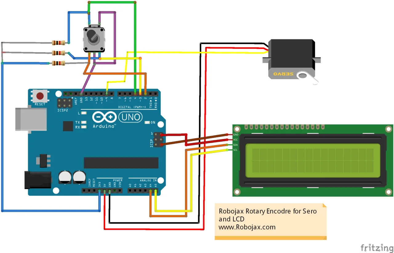
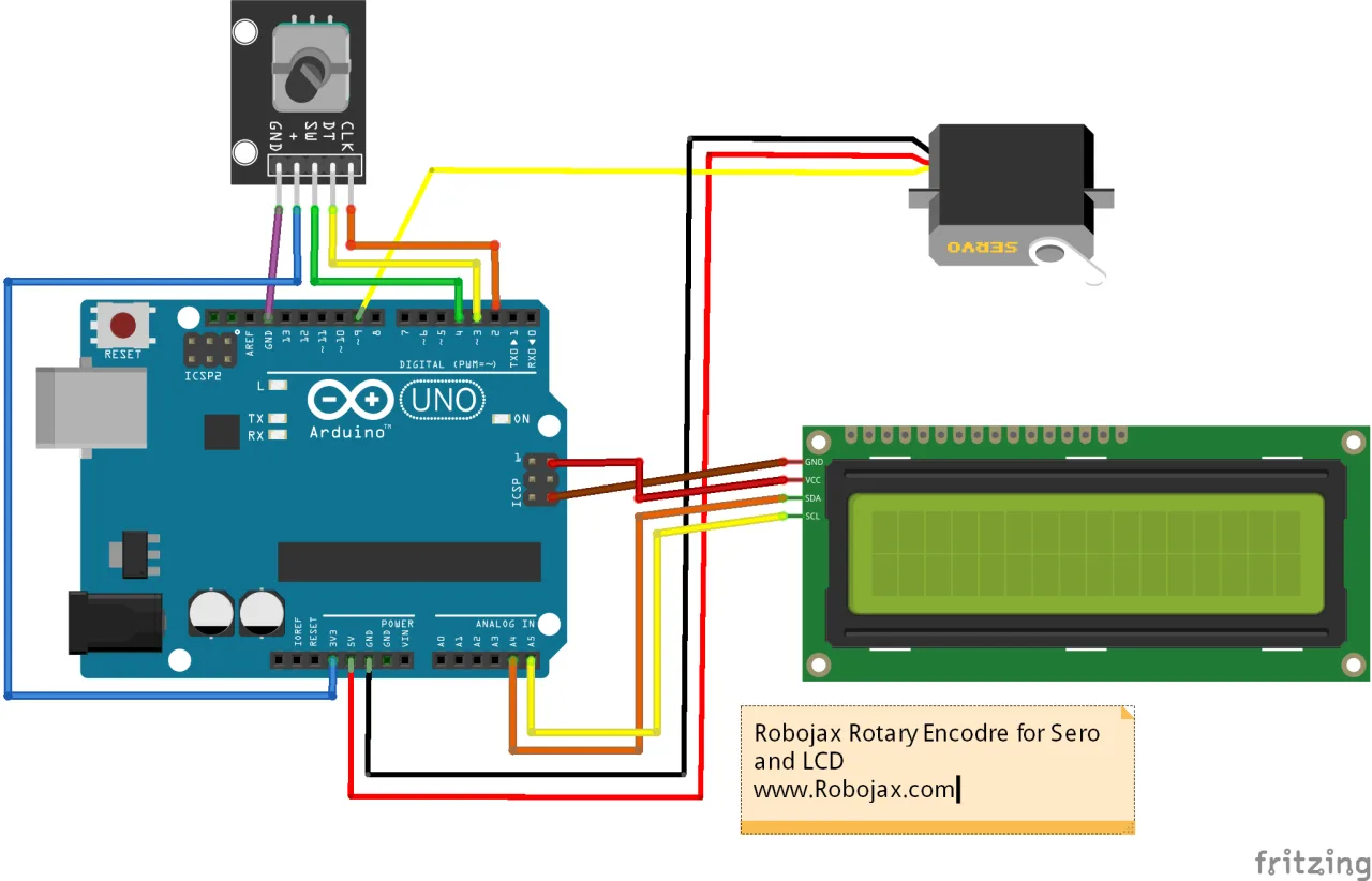
이 프로젝트에는 연결할 세 가지 주요 구성 요소가 있습니다: 로터리 엔코더, 서보 모터 및 I2C LCD. 아래 배선 다이어그램은 필요한 모든 연결을 보여줍니다. (비디오 05:35)
로터리 엔코더 모듈이 기본 입력입니다. CLK 및 DT 핀은 Arduino 디지털 핀 2와 3에 연결됩니다. "+" 핀은 3.3V에 연결되고 "GND" 핀은 접지에 연결됩니다. 베어 엔코더를 사용하는 경우 다이어그램에 표시된 대로 엔코더의 두 데이터 핀과 스위치 핀에서 3.3V로 3개의 풀업 저항(1kΩ ~ 100kΩ)을 추가해야 합니다. (비디오 07:03)
서보 모터에는 세 개의 와이어가 있습니다. 신호 와이어(일반적으로 노란색 또는 주황색)는 PWM 지원 핀에 연결되며, 이 예에서는 핀 9입니다. 전원 와이어(일반적으로 빨간색)는 5V에 연결되고 접지 와이어(일반적으로 갈색 또는 검은색)는 접지에 연결됩니다. 높은 토크 서보의 경우 Arduino의 전압 조정기에 과부하가 걸리지 않도록 외부 5V 전원 공급 장치를 사용하는 것이 좋습니다. (비디오 06:03)
I2C LCD에는 네 개의 연결이 필요합니다. VCC 핀은 5V에, GND는 접지에, SDA는 Arduino의 A4 핀에, SCL은 A5 핀에 연결됩니다. 또는 ICSP 헤더의 5V 핀에서 LCD에 전원을 공급할 수 있습니다. (비디오 06:31)
필요한 라이브러리 설치
코드를 업로드하기 전에 두 개의 라이브러리를 설치해야 합니다. 첫 번째는 LiquidCrystal_I2C 라이브러리로, 제공된 ZIP 파일을 다운로드하고 Sketch → Include Library → Add .ZIP Library 메뉴를 사용하여 추가할 수 있습니다. (비디오 13:28)
두 번째는 Paul Stoffregen의 Encoder 라이브러리입니다. 이 라이브러리는 Sketch → Include Library → Manage Libraries로 이동하여 "encoder"를 검색하고 설치를 클릭하면 라이브러리 관리자를 통해 직접 설치할 수 있습니다. (비디오 13:59)
코드 설명
코드는 높은 구성 가능성을 갖도록 설계되었습니다. 주요 매개변수는 모두 스케치 상단에 정의되어 있어 로직을 파고들지 않고도 동작을 쉽게 조정할 수 있습니다. (비디오 17:52)
const int SW_PIN = 4;//로터리 엔코더 스위치용 핀 정의
const int PIN_A =2;
const int PIN_B =3;
const int homePosition = 90; //초기 위치
const int stepValue = 3;//노브를 돌릴 때 서보가 회전해야 하는 속도
const int servoPin = 9;//~로 표시된 핀이어야 함SW_PIN,PIN_A및PIN_B: 이 상수는 엔코더의 스위치, CLK 및 DT 핀에 각각 연결된 Arduino 핀을 정의합니다. 다른 핀을 사용하는 경우 이 값을 변경하십시오.homePosition: 엔코더의 푸시 버튼 스위치를 누를 때 서보가 이동할 각도(도 단위)입니다. 0에서 180 사이의 값으로 변경할 수 있습니다.stepValue: 제어 감도를 제어합니다. 엔코더의 각 디텐트(클릭)마다 서보 각도가 변경되는 도 수를 결정합니다. 값이 높을수록 서보가 더 빠르게 움직이고, 값이 낮을수록 더 미세한 제어가 가능합니다.servoPin: 서보의 신호 와이어가 연결된 PWM 핀입니다. Arduino 보드에서 이 핀 옆에 "~" 기호가 있는지 확인하십시오. 이러한 핀만 필요한 PWM 신호를 생성할 수 있기 때문입니다.
코드에는 사용자 정의 함수인 lcdAngel(int angel)도 포함되어 있습니다. 이 함수는 LCD에 각도 값을 업데이트하는 역할을 합니다. 먼저 디스플레이에서 이전 숫자를 지운 다음, 새 각도와 도 기호(°)를 출력합니다. 이 함수는 서보 각도가 변경될 때마다 자동으로 호출되므로 직접 상호작용할 필요가 없습니다. (영상 27:56 부분)
인코더로 서보를 구동하는 방법은 레슨 97-2: 로터리 인코더를 사용하여 서보 모터 제어하기에서 다룹니다.
실시간 프로젝트 시연
코드가 업로드되면 LCD는 먼저 "Robojax Encoder" 및 "Servo Test" 시작 화면을 2초 동안 표시한 다음 지우고 현재 각도를 표시합니다. (영상 24:10 부분)
인코더를 회전하면 서보가 새 위치로 부드럽게 이동하고 각도가 LCD에 업데이트됩니다. 회전 방향에 따라 각도가 증가하거나 감소합니다. 방향이 반대로 느껴지면 PIN_A와 PIN_B 연결 또는 코드에서의 정의를 간단히 바꾸면 됩니다. (영상 17:32 부분)
서보의 움직임은 0도에서 180도 사이로 제한됩니다. 이 한계를 넘어 인코더를 계속 회전하면 서보가 경계에서 멈추어 기계적 손상을 방지합니다. (영상 25:54 부분)
인코더에 내장된 푸시 버튼 스위치를 누르면 서보가 정의한 homePosition으로 즉시 돌아갑니다. 이는 알려진 기준점 또는 "홈" 위치를 설정하는 데 유용합니다. (영상 27:13 부분)
이 비디오의 관련 프로젝트
챕터
- [00:01] 로터리 인코더로 서보 제어 소개
- [01:46] 가변 저항 대신 로터리 인코더를 사용하는 이유
- [05:35] PCB 버전 로터리 인코더 배선
- [07:03] 저항이 있는 베어 로터리 인코더 배선
- [12:05] I2C LCD 디스플레이 연결
- [13:28] 필요한 라이브러리 설치
- [14:54] 기본 인코더 예제 코드 이해
- [17:52] 서보 및 스위치용 코드 수정
- [20:20] 서보 및 LCD 제어를 위한 전체 코드 설명
- [30:01] 프로젝트 실시간 시연
이미지
/*
 * Lesson 97-3: Controlling Servo Motor using Rotary Encoder and Display Angle on LCD
 Download and resource page https://robojax.com/RJT453

 *  Watch full details video: https://youtu.be/6xVLbNlmK-g
  This video is part of Arduino Step by Step Course which starts here: https://youtu.be/-6qSrDUA5a8


If you found this tutorial helpful, please support me so I can continue creating
content like this. Make a donation using PayPal by credit card https://bit.ly/donate-robojax

 * This code is "AS IS" without warranty or liability. Free to be used as long as you keep this note intact.*
 * This code has been downloaded from Robojax.com
    This program is free software: you can redistribute it and/or modify
    it under the terms of the GNU General Public License as published by
    the Free Software Foundation, either version 3 of the License, or
    (at your option) any later version.

    This program is distributed in the hope that it will be useful,
    but WITHOUT ANY WARRANTY; without even the implied warranty of
    MERCHANTABILITY or FITNESS FOR A PARTICULAR PURPOSE.  See the
    GNU General Public License for more details.

    You should have received a copy of the GNU General Public License
    along with this program.  If not, see <https://www.gnu.org/licenses/>.
 *  Updated by Ahmad Shamshiri on Jan 23, 2022
 *  Encoder Library - Basic Example
 * http://www.pjrc.com/teensy/td_libs_Encoder.html
 *
 * This example code is in the public domain.
 */
const int SW_PIN = 4;//define a pin for rotary encode switch
const int PIN_A =2;
const int PIN_B =3;

#include <Encoder.h>

// Change these two numbers to the pins connected to your encoder.
//   Best Performance: both pins have interrupt capability
//   Good Performance: only the first pin has interrupt capability
//   Low Performance:  neither pin has interrupt capability
Encoder myEnc(PIN_A, PIN_B);
//   avoid using pins with LEDs attached

const int homePosition = 90; //initial position
const int stepValue = 3;//how fast the servo should rotate when turning the knob
const int servoPin = 9;//~must be a pin that that is labeled with ~
#include <Servo.h>

Servo myservo;  // create servo object to control a servo
int servoAngel =homePosition;


#include <Wire.h>
#include <LiquidCrystal_I2C.h>
// Set the LCD address to 0x27 or 0x3F for a 16 chars and 2 line display
LiquidCrystal_I2C lcd(0x3F, 16, 2);

void setup() {
  Serial.begin(9600);
  pinMode(SW_PIN, INPUT);
  Serial.println("Robojax Encoder with LCD and Servo");
   myservo.attach(servoPin);  // attaches the servo on pin
   myservo.write(servoAngel);//move servo to initial position

  lcd.begin();
  // Turn on the blacklight and print a message.
  lcd.backlight();
  lcd.print("Robojax Encoder");
  lcd.setCursor (0,1); // go to start of 2nd line
  lcd.print("Servo Test");
  delay(2000);
   lcd.clear();// clear previous values from screen
  lcd.print("Robojax Encoder");
  lcd.setCursor (0,1); // go to start of 2nd line
  lcd.print("Angle: ");
}

long oldPosition  = -999;

void loop() {
  long newPosition = myEnc.read();
  if (newPosition != oldPosition) {

    if(newPosition >  oldPosition)
    {
    int newStep = abs(newPosition - oldPosition);
      Serial.print("Angle ");
      Serial.println(servoAngel);
      servoAngel -= stepValue;
      if(servoAngel <0)
          servoAngel =0;
      myservo.write(servoAngel); //move servo to new angle
      lcdAngel(servoAngel);//print on LCD
    }

    if(newPosition <  oldPosition )
    {
    int newStep = abs(newPosition - oldPosition);
      Serial.print("Angle ");
      Serial.println(servoAngel);
      servoAngel += stepValue;
      if(servoAngel >180)
          servoAngel =180;
      myservo.write(servoAngel); //move servo to new angle
      lcdAngel(servoAngel);//print on LCD
    }
   oldPosition = newPosition;//remember the new position
  }

  if( digitalRead(SW_PIN) == LOW)
  {
    Serial.print("Home: ");
    Serial.println(homePosition);
    servoAngel =homePosition;
      myservo.write(servoAngel); //move servo to new angle
      lcdAngel(servoAngel);//print on LCD

  }

  //delay(200);
}

/*
 * lcdAngel(int angel)
 * prints the angle on LCD
 * written by Ahmad Shamshiri
 * www.robojax.com
 * Jan 27, 2022 at 13:18
 * Watch full details video: https://youtu.be/6xVLbNlmK-g
 */
void lcdAngel(int angel)
{

  int startChar =7;
  for(int i=startChar; i<16; i++)
  {
   lcd.setCursor (i,1);
    lcd.print(" ");
  }

   lcd.setCursor (startChar,1); // line 1
   lcd.print(angel);
   lcd.print((char)223);
}
필요할 수 있는 것들
-
아마존
-
아마존
-
아마존
-
이베이
-
이베이
-
알리익스프레스Purchase an LCD1602 from AliExpresss.click.aliexpress.com
자원 및 참고자료
-
외부Purchase an LCD1602 from AliExpresss.click.aliexpress.com
-
외부
-
외부
-
외부Purchase ZK-5DA from Amazon UKamzn.to
파일📁
파일이 없습니다.