Lesson 102: Using ZK-5DA to Control Two 4A DC Motors
In this tutorial, we will explore how to use the ZK-5DA motor driver module to control two 4A DC motors. This module is based on the TA6586 chip, which offers efficient motor control with low voltage drop and heat dissipation. By the end of this tutorial, you will be able to start, stop, and control the speed of the motors effectively. For additional clarification, be sure to check the video at (in video at 08:55).

Hardware Explained
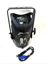
The main component of this project is the ZK-5DA motor driver module. It uses the TA6586 chip, which allows for efficient control of two DC motors. This chip is designed to handle up to 4A of current per motor while maintaining a low voltage drop, which helps in reducing heat generation during operation.
In addition to the motor driver, you will need an Arduino board to send control signals to the module. The Arduino will define the direction and speed of the motors using PWM (Pulse Width Modulation) signals. Connecting the motors to the appropriate terminals on the driver module allows for directional control and speed adjustments.
Datasheet Details
| Manufacturer | RZ Semiconductor |
|---|---|
| Part number | TA6586 |
| Operating voltage | 3–14 V |
| Peak current | 9 A |
| Continuous current | 5 A |
| Standby current | < 2 µA |
| Voltage drop | 400 mV at 4 A |
| Temperature range | -25 to 85 °C |
| Package | Standard IC package |
| Notes / variants | Thermal shutdown, overcurrent protection |
- Ensure proper heat dissipation for continuous operation above 3 A.
- Use PWM-enabled pins for speed control.
- Verify voltage ratings before connecting motors.
- Pay attention to wiring polarity to avoid motor damage.
- Monitor temperature during operation to prevent overheating.
Wiring Instructions

To wire the ZK-5DA motor driver module, start by connecting the power supply. Connect the positive terminal of your power source to the '+' terminal on the motor driver and the negative terminal to the '-' terminal. The two motors will be connected to the output terminals, which are labeled for clarity.
For the Arduino connections, use the PWM-enabled pins: connect pin 3 to the control pin for motor 1, and pin 5 to the second control pin for motor 1. Similarly, connect pin 6 to the control pin for motor 2, and pin 9 to the second control pin for motor 2. Finally, ensure that all grounds are connected together.
Code Examples & Walkthrough
The code starts by defining the relevant pins and initializing the serial monitor for debugging. The motor control functions, such as M1 and M2, handle the motor directions and speeds.
const int D0=9; // Motor 1 PWM pin
const int D1=6; // Motor 1 direction pin
const int D2=5; // Motor 2 PWM pin
const int D3=3; // Motor 2 direction pin
Here, the pins are set up to control the motors using PWM signals. The setup function initializes these pins as outputs.
void loop() {
  M2(CW, 80); // Motor 2 runs clockwise at 80% speed
  delay(3000); // Wait for 3 seconds
  brake(2); // Apply brake to motor 2
  delay(1000);
}
This excerpt shows the main loop of the program, where motor 2 is set to run clockwise at 80% speed for 3 seconds before applying the brake. The brake function stops the motor when called.
void M1(bool direction, int speed) {
  int pwm = map(speed, 0, 100, 0, 255); // Map speed to PWM range
  if (direction == CW) {
    analogWrite(D0, pwm);
    analogWrite(D1, LOW);
  } else {
    analogWrite(D1, pwm);
    analogWrite(D0, LOW);
  }
}
The M1 function takes the direction and speed as inputs, maps the speed to a PWM value, and sets the appropriate pins to control the motor's rotation direction. The debugPrint function is called to show the current state in the serial monitor.
For the complete code, remember to check below the article (in video at 08:55).
Demonstration / What to Expect
When you run the code, expect the motors to start rotating in the specified directions at the set speeds. The code includes braking and speed adjustments, allowing for dynamic control. If the motors do not respond as expected, double-check your wiring connections and ensure that the correct pins are configured in the code. Additionally, be cautious of overheating, particularly when drawing high currents, as indicated during the test (in video at 23:23).
Video Timestamps
- 00:00 Introduction
- 03:16 Datasheet viewed
- 06:34 Wiring Explained
- 08:55 Code Explained
- 14:28 Demonstration: Motor Control
- 17:22 Demonstration: Maximum current test
- 23:23 Voltage Drop test at 3A, 4A and 5A
- 26:28 Conclusion remarks
Images
/*
 * Lesson 102: Using ZK-5DA to control 2 DC motors, each 4A
 *
 * Full video details: https://youtu.be/W_Wm28nQAYA
 * Video timing:
00:00 Introduction
03:16 Datasheet viewed
06:34 Wiring explained
08:55 Code explained
14:28 Demonstration: Motor control
17:22 Demonstration: Maximum current test
23:23 Voltage drop test at 3A, 4A, and 5A
26:28 Conclusion remarks

 * Written by Ahmad Shamshiri for Arduino Step by Step Course by Robojax
 * www.Robojax.com
 * on Mar 22, 2022

 *
 * This code is part of Arduino Step by Step Course which starts here:  https://youtu.be/-6qSrDUA5a8
 *
 * For the library for this code, visit http://robojax.com/
 *
If you found this tutorial helpful, please support me so I can continue creating
content like this. Make a donation using PayPal or a credit card: https://bit.ly/donate-robojax
 * This code is "AS IS" without warranty or liability. Free to be used as long as you keep this note intact.
 * This code has been downloaded from Robojax.com
    This program is free software: you can redistribute it and/or modify
    it under the terms of the GNU General Public License as published by
    the Free Software Foundation, either version 3 of the License, or
    (at your option) any later version.

    This program is distributed in the hope that it will be useful,
    but WITHOUT ANY WARRANTY; without even the implied warranty of
    MERCHANTABILITY or FITNESS FOR A PARTICULAR PURPOSE.  See the
    GNU General Public License for more details.

    You should have received a copy of the GNU General Public License
    along with this program.  If not, see <https://www.gnu.org/licenses/>.
 */


 //all pins must be PWM enabled pins with ~ printed beside them
const int D0=9;//~
const int D1=6;
const int D2=5;
const int D3=3;

bool CW = true;
bool CCW = false;


bool debug = false;

void setup() {
  Serial.begin(9600);
  Serial.println("Robojax TA6586 Motor Control");
 pinMode(D0, OUTPUT);
 pinMode(D1, OUTPUT);
 pinMode(D2, OUTPUT);
 pinMode(D3, OUTPUT);


}

void loop() {
  // * Full video details: https://youtu.be/W_Wm28nQAYA
  M2(CW, 80);//motor 1 runs CW at 80% speed
  M1(CW, 100); //motor 1 runs CW at 100% speed
  delay(3000);//wait for 3 seconds
  brake (2);//apply brake to motor 2
  delay(1000);

  M2(CCW, 60);//motor 2 runs CCW at 60% speed
  delay(3000);//wait for 3 seconds
  brake (2);//apply brake to motor 2
  brake (1);//apply brake to motor 1
  delay(3000);//wait for 3 seconds
  for(int i=0; i<=100; i++)
  {
    M1(CCW, i);//run motor 1 to CCW direction with i% speed
    delay(100);
  }
  delay(2000);
  brake (2);//apply brake to motor 2
  delay(3000); delay(3000);//wait for 3 seconds}
}//loop ends

/*
 *  M1(bool direction,int speed)
 * @brief runs motor 1
 * @param direction is CW or CCW,
 * @param speed is an integer between 0 to 100

 * @return returns none
 * Written by Ahmad Shamshiri for robojax.com
 * on Mar 22, 2022
 * Full video details: https://youtu.be/W_Wm28nQAYA
 */
void M1(bool direction,int speed)
{
  int pwm=map(speed, 0, 100, 0, 255);
  if(direction == CW)
  {
   analogWrite(D0,pwm);
   analogWrite(D1,LOW);
  }else{
   analogWrite(D1,pwm);
   analogWrite(D0,LOW);
  }
  debugPrint(1, direction, speed, false);
}//M1 end


/*
 *  M2(bool direction,int speed)
 * @brief runs motor 2
 * @param direction is CW or CCW,
 * @param speed is an integer between 0 to 100

 * @return returns none
 * Written by Ahmad Shamshiri for robojax.com
 * on Mar 22, 2022
 * Full video details: https://youtu.be/W_Wm28nQAYA
 */
void M2(bool direction,int speed)
{
  int pwm=map(speed, 0, 100, 0, 255);
  if(direction == CW)
  {
   analogWrite(D2,pwm);
   analogWrite(D3,LOW);
  }else{
   analogWrite(D3,pwm);
   analogWrite(D2,LOW);
  }
  debugPrint(2, direction, speed, false);
}//M2 ends


/*
 *  brake(int motor)
 * @brief applies brake to a motor
 * @param motor is an integer (1 or 2)

 * @return returns none
 * Written by Ahmad Shamshiri for robojax.com
 * on Mar 22, 2022
 * Full video details: https://youtu.be/W_Wm28nQAYA
 */
void brake(int motor)
{
   if(motor == 1)
  {
   analogWrite(D0,HIGH);
   analogWrite(D1,HIGH);
  }else{
   analogWrite(D2,HIGH);
   analogWrite(D3,HIGH);
  }
  debugPrint(motor, true,  0, true);
}//brake ends


/*
 * debugPrint(int motor, bool direction, int speed, bool stop)
 * @brief prints debugging information
 * @param motor is an integer (1 or 2)
 * @param direction is CW or CCW
 * @param speed is an integer from 0 to 100
 * @param stop is true or false; if true, the word "stop" is printed

 * @return returns none
 * Written by Ahmad Shamshiri for robojax.com
 * on Mar 22, 2022
 * Full video details: https://youtu.be/W_Wm28nQAYA
 */
void debugPrint(int motor, bool direction, int speed, bool stop)
{
  if(debug)
  {
      Serial.print("Motor: ");
      Serial.print(motor);
    if(stop && motor>0)
    {
      Serial.println(" Stopped");
    }else{
      if(direction)
      {
      Serial.print(" CW at ");
      }else{
       Serial.print(" CCW at ");
      }
      Serial.print(speed);
      Serial.println(" %");
    }
  }//debug

}

//not used but can be used to apply brake on both motors
void fullBrake()
{
 brake(1);
 brake(2);

}
Things you might need
-
AliExpressPurchase ZK-5DA from AliExpresss.click.aliexpress.com
Resources & references
-
ExternalPurchase ZK-5DA from AliExpresss.click.aliexpress.com
-
External
-
External
-
ExternalPurchase ZK-5DA from Amazon UKamzn.to
-
ExternalPurchase ZK-5DA from Amazon, USAamzn.to
Files📁
Datasheet (pdf)
-
TA6586 motor Driver datasheet
TA6586_motor_Driver_datasheet.pdf0.22 MB