บทเรียนนี้เป็นส่วนหนึ่งของ: บทเรียนที่ 107 28BYJ-48 โปรเจกต์สำหรับเครื่องสเต็ปเปอร์ 8
วิดีโอนี้มี 8 โปรเจ็กต์ แต่ละโปรเจ็กต์มีโค้ดแยกกัน ลิงก์ไปยังวิดีโออื่นๆ อยู่ด้านล่างบทความนี้
บทเรียน 107-8: การควบคุมความเร็วของสเต็ปเปอร์มอเตอร์ 28BYJ-48 โดยใช้โพเทนชิโอมิเตอร์
โปรเจกต์ 8: การควบคุมมอเตอร์สเต็ปเปอร์ด้วยโพเทนชิโอมิเตอร์ – มอเตอร์สเต็ปเปอร์ 28BYJ-48
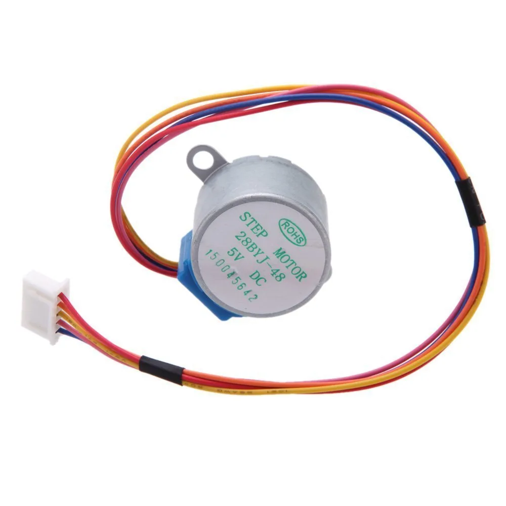
บทความนี้นำเสนอส่วนสุดท้ายของซีรีส์ 8 โปรเจกต์เกี่ยวกับการควบคุมมอเตอร์สเต็ปเปอร์ 28BYJ-48 ร่วมกับ Arduino ในโปรเจกต์ 8 มอเตอร์สเต็ปเปอร์ถูกควบคุมผ่านโพเทนชิโอมิเตอร์ ซึ่งช่วยให้ผู้ใช้สามารถเปลี่ยนความเร็วและทิศทางของมอเตอร์ได้แบบไดนามิกเพียงแค่หมุนปุ่ม วิธีการอินพุตแบบแอนะล็อกนี้เป็นแนวทางการควบคุมที่ใช้งานง่ายและหลากหลาย นำไปประยุกต์ใช้ได้อย่างกว้างขวางในระบบหุ่นยนต์และระบบควบคุมการเคลื่อนไหว
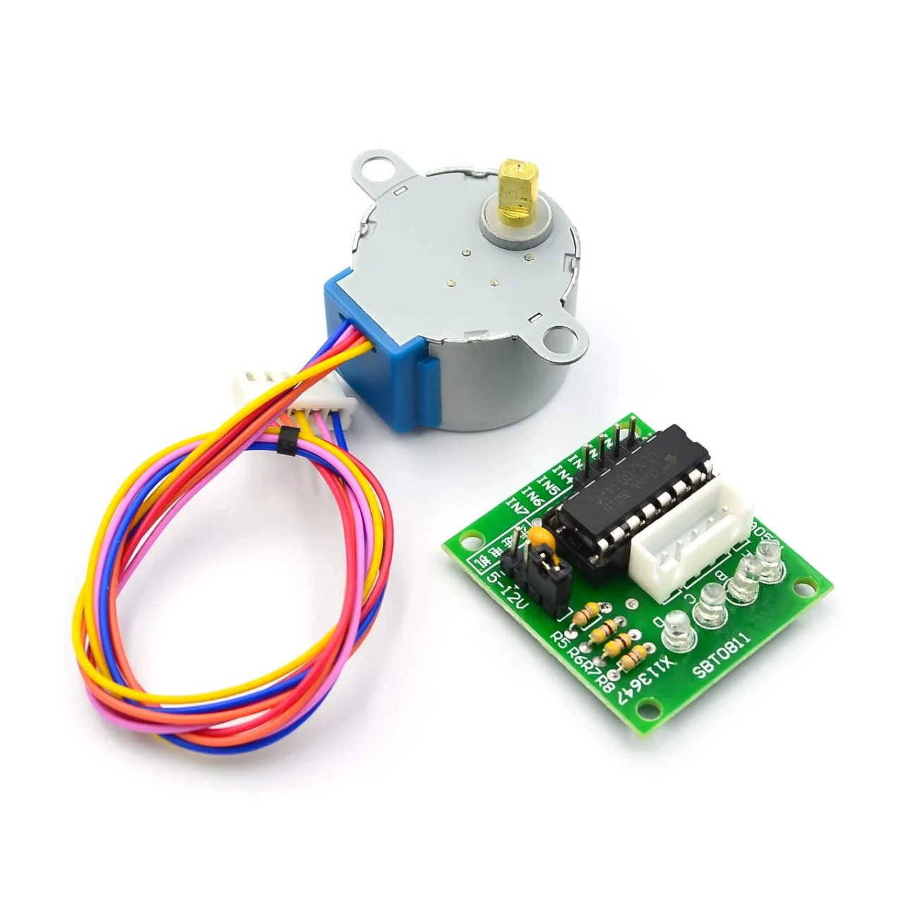
แผนผังการเดินสายไฟและโค้ดทั้งหมดสำหรับโปรเจกต์นี้สามารถดาวน์โหลดได้ด้านล่างบทความ
📘 บทนำ
การตั้งค่านี้ใช้โพเทนชิโอมิเตอร์แบบแอนะล็อกที่เชื่อมต่อกับ Arduino เพื่ออ่านค่าแรงดันไฟฟ้าที่แปรผันระหว่าง 0 ถึง 1023 จากอินพุตนี้ ความเร็วและทิศทางของมอเตอร์จะถูกปรับแบบไดนามิก:
-
การหมุนโพเทนชิโอมิเตอร์ตามเข็มนาฬิกาจะเพิ่มความเร็วในทิศทางหนึ่ง
-
การหมุนทวนเข็มนาฬิกาจะกลับทิศทาง
⚙️ การเดินสายไฟ
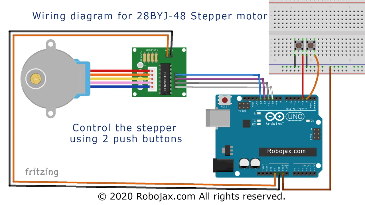
โปรเจกต์นี้เชื่อมต่อโพเทนชิโอมิเตอร์และมอเตอร์สเต็ปเปอร์เข้ากับ Arduino ดังนี้:
-
ขากลางของโพเทนชิโอมิเตอร์ → ขาแอนะล็อก A0
-
อีกสองขา → 5V และ GND
-
ไดรเวอร์ ULN2003 → ขา 8, 10, 9, 11 สำหรับมอเตอร์สเต็ปเปอร์
คำอธิบายภาพ: การเดินสายไฟโปรเจกต์ 8: โพเทนชิโอมิเตอร์อ่านค่าอินพุตแอนะล็อกเพื่อควบคุมความเร็วและทิศทาง
💻 คำอธิบายโค้ด
โค้ดอ่านค่าแอนะล็อกและแปลงเป็นความเร็วและทิศทาง:
-
รวมไลบรารีและกำหนดขา:
#include <Stepper.h>
const int stepsPerRevolution = 2048;
Stepper myStepper(stepsPerRevolution, 8, 10, 9, 11);-
ฟังก์ชัน Setup:
void setup() {
  Serial.begin(9600);
  myStepper.setSpeed(10);
}-
ฟังก์ชัน Loop พร้อมการควบคุมด้วยโพเทนชิโอมิเตอร์:
void loop() {
  int sensorValue = analogRead(A0);
  int speed = map(sensorValue, 0, 1023, -15, 15);

  if (speed != 0) {
    myStepper.setSpeed(abs(speed));
    myStepper.step((speed > 0) ? 1 : -1);
  }
  delay(2);
}-
ฟังก์ชัน
map()แปลงค่า 0–1023 เป็น -15 ถึง +15 รอบต่อนาที -
ความเร็วและทิศทางเปลี่ยนแปลงแบบเรียลไทม์เมื่อหมุนโพเทนชิโอมิเตอร์
-
abs(speed)รับประกันค่าบวกของรอบต่อนาที ส่วนทิศทางถูกจัดการในstep()
🎬 ไทม์สแตมป์จากวิดีโอเต็ม
นี่คือไทม์สแตมป์สำคัญของวิดีโอสำหรับโปรเจกต์นี้:
-
1:39:24 – โปรเจกต์ 8: บทนำ
-
1:40:58 – โปรเจกต์ 8: การเดินสายไฟ
-
1:44:04 – โปรเจกต์ 8: โค้ด
-
1:53:19 – โปรเจกต์ 8: การสาธิต
ภาพ
บทเรียนนี้เป็นส่วนหนึ่งของ: บทเรียนที่ 107 28BYJ-48 โปรเจกต์สำหรับเครื่องสเต็ปเปอร์ 8
- บทเรียน 107-1: เริ่มและหยุดมอเตอร์สเต็ปเปอร์ 28BYJ-48 พร้อมกำหนดทิศทางในโค้ด
- บทเรียน 107-2: การควบคุมมอเตอร์สเต็ปเปอร์ 28BYJ-48 ผ่าน Serial Monitor
- บทเรียน 107-3: การควบคุมมอเตอร์สเต็ปเปอร์ 28BYJ-48 โดยใช้ปุ่มกดสามปุ่ม: หมุนตามเข็มนาฬิกา (CW), หมุนทวนเข็มนาฬิกา (CCW), และหยุด (STPB-1)
- บทเรียนที่ 107-4: การควบคุมมอเตอร์สเต็ปเปอร์ 28BYJ-48 โดยใช้ปุ่มกดสองปุ่ม ตามเข็มนาฬิกา ทวนเข็มนาฬิกา (กดค้างไว้) STPB-2
- บทเรียน 107-5: ส่งมอเตอร์ 28BYJ-48 หมุนหนึ่งรอบในทิศทางตามเข็มนาฬิกาหรือทวนเข็มนาฬิกา, STPB-3
- บทเรียน 107-6: การควบคุมมอเตอร์สเต็ปเปอร์ 28BYJ-48 โดยใช้ปุ่มกดสามปุ่ม พร้อมด้วยมุมและความเร็ว STPB-4
- บทเรียน 107-7: การส่งสเต็ปเปอร์มอเตอร์ 28BYJ-48 ไปยังมุมใดๆ ด้วยปุ่มกด STPB-5 ที่กำหนดไว้
++
/*
* Lesson 107-8:  * This is Arduino code to control the speed of a 28BYJ-48
* stepper motor with a potentiometer.
See the video for details and a demonstration.

In this lesson, we learn how to use a mini stepper motor, the 28BYJ-48, for our projects. I am presenting eight projects
  so you can use it in almost any application. In the video, I have explained the code, shown the full wiring diagram, and
  how to connect the wires, push buttons, and breadboard.

  Project 1: Running motor
  Project 2: Controlling stepper motor from Serial Monitor
  Project 3: Controlling stepper motor using push button STPB-1
  Project 4: Controlling using push button STPB-2  keep pressing
  Project 5: One Revolution using push button STPB-3
  Project 6: Push button for any angle and speed STPB-4
  Project 7: Using multiple buttons for any angle STPB-5 (angle, speed and direction)
  Project 8: Controlling stepper motor using potentiometer (this code)

  * Watch the video instruction for this code: https://youtu.be/TQ7R2bY-MWU
  *
  * This code is part of the Arduino Step by Step Course, which starts here:  https://youtu.be/-6qSrDUA5a8
  *
  * For the library for this code, visit http://robojax.com/
  *
 If you found this tutorial helpful, please support me so I can continue creating
 content like this. Make a donation using PayPal or a credit card: https://bit.ly/donate-robojax

 * Written by Ahmad Shamshiri for Robojax Robojax.com
 * on June 30, 2019 at 19:04 in Ajax, Ontario, Canada
 *
 *
  *  * This code is "AS IS" without warranty or liability. Free to be used as long as you keep this note intact.*
  * This code has been downloaded from Robojax.com
     This program is free software: you can redistribute it and/or modify
     it under the terms of the GNU General Public License as published by
     the Free Software Foundation, either version 3 of the License, or
     (at your option) any later version.

     This program is distributed in the hope that it will be useful,
     but WITHOUT ANY WARRANTY; without even the implied warranty of
     MERCHANTABILITY or FITNESS FOR A PARTICULAR PURPOSE.  See the
     GNU General Public License for more details.

     You should have received a copy of the GNU General Public License
     along with this program.  If not, see <https://www.gnu.org/licenses/>.

 */

const int desiredValue = 20;//time in sec for a Revolution

const int dir = 2; // 1 for CW and 2 for CCW

int Pin1 = 10;//IN1 is connected to 10
int Pin2 = 11;//IN2 is connected to 11
int Pin3 = 12;//IN3 is connected to 12
int Pin4 = 13;//IN4 is connected to 13
int potPin = A0;// center pin of pot is connected to this pin
int vcc2 = 2;// additional 5V for potentiometer

int pole1[] ={0,0,0,0, 0,1,1,1, 0};//pole1, 8 step values
int pole2[] ={0,0,0,1, 1,1,0,0, 0};//pole2, 8 step values
int pole3[] ={0,1,1,1, 0,0,0,0, 0};//pole3, 8 step values
int pole4[] ={1,1,0,0, 0,0,0,1, 0};//pole4, 8 step values


int poleStep = 0;
int calcDelayfromTime(int t);
void driveStepper(int c);
int N = calcDelayfromTime(desiredValue);


void setup()
{
 pinMode(Pin1, OUTPUT);//define pin for ULN2003 in1
 pinMode(Pin2, OUTPUT);//define pin for ULN2003 in2
 pinMode(Pin3, OUTPUT);//define pin for ULN2003 in3
 pinMode(Pin4, OUTPUT);//define pin for ULN2003 in4
 pinMode(vcc2, OUTPUT);//define pin as output for 5V for pot
 digitalWrite(vcc2, HIGH);//set vcc2 pin HIGH to have 5V for pot
 Serial.begin(9600);
 Serial.println("Robojax Stepper Control");
 Serial.print("Max time per rev set: ");
 Serial.print(desiredValue);
 Serial.print(" loop delay: ");
 Serial.println(N);
  delay(4000);//give use time to read
}// setup

 void loop()
{
  // Robojax Stepper code S8BYJ-48
 if(dir ==1){
   poleStep++;
    driveStepper(poleStep);
 }else if(dir ==2){
   poleStep--;
    driveStepper(poleStep);
 }else{
  driveStepper(8);
 }
 if(poleStep>7){
   poleStep=0;
 }
 if(poleStep<0){
   poleStep=7;
 }
 int potValue =analogRead(potPin);// read potentiometer value
 int speed = map(potValue,0, 1023, 1,N);

 delay(speed);


}// loop

int calcDelayfromTime(int t){
  return ((t-5)/4)+1;
}//


/*
 * @brief sends signal to the motor
 * @param c is an integer representing the pole of the motor
 * @return does not return anything
 *
 * www.Robojax.com code June 2019
 */
void driveStepper(int c)
{
     digitalWrite(Pin1, pole1[c]);
     digitalWrite(Pin2, pole2[c]);
     digitalWrite(Pin3, pole3[c]);
     digitalWrite(Pin4, pole4[c]);
}//driveStepper end here
สิ่งที่คุณอาจต้องการ
-
อเมซอน
-
อเมซอน
-
อาลีเอ็กซ์เพรสPurchase 5 pcs 28BYJ-48 stepper motors from AliExpresss.click.aliexpress.com
แหล่งข้อมูลและเอกสารอ้างอิง
-
ภายนอก
-
ภายนอก
-
ภายนอก
ไฟล์📁
ไฟล์ Fritzing
-
28BYJ-48 Stepper Motor
28BYJ-48 Stepper Motor.fzpz0.01 MB