Bu eğitim şunun parçasıdır: Ders 107 28BYJ-48 Stepper 8 Projeleri
Bu videoda 8 proje bulunmaktadır. Her projenin ayrı kodu vardır. Diğer videolara ait bağlantılar bu yazının altında yer almaktadır.
Ders 107-4: 28BYJ-48 Step Motorunun İki Buton Kullanılarak Kontrol Edilmesi, CW, CCW (Basılı Tutma), STPB-2
Proje 4: STPB-2 – 28BYJ-48 Step Motoru Kullanarak Basılı Tut ve Çalıştır
Bu makale, Arduino ile 28BYJ-48 step motorunu kontrol etmeye yönelik 8 eğitici serisinin dördüncü projesini kapsar. Bu projede, step motoru STPB-2 etiketli bir basma düğmesi kullanılarak kontrol edilir. Önceki projede tek bir basışın bir tam devri tetiklediği durumun aksine, bu kurulum motorun yalnızca düğmeye basılı tutulduğu sürece dönmesini sağlar.
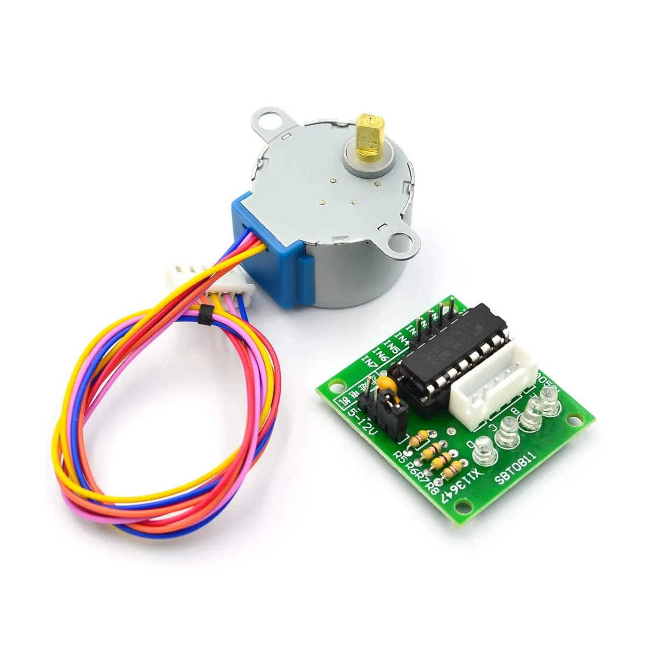
Bu projenin tüm kaynak kodu ve bağlantı şemaları makalenin altında mevcuttur.
📘 Giriş
Bu proje, anlık bir basma düğmesi kullanarak sürekli motor kontrol mekanizmasını gösterir. Kullanıcı düğmeye bastığında, motor sürekli olarak ileri adım atar. Düğme bırakıldığı anda motor durur. Bu yöntem, endüstriyel makinelerde ve test düzeneklerinde jog kontrollerinde yaygındır.
⚙️ Bağlantı Şeması
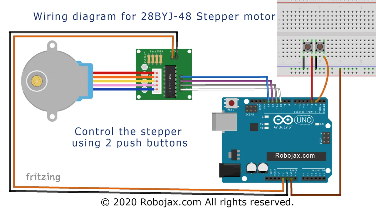
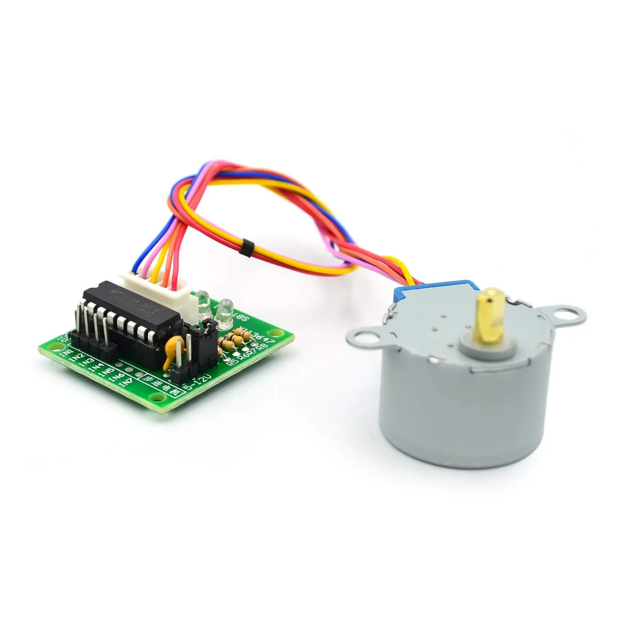
Step motoru ve ULN2003 için bağlantılar aynı kalır. Düğme şu şekilde bağlanır:
-
Basma düğmesi STPB-2'nin bir ucu → Arduino pin 2
-
Diğer uç → GND
-
Dahili pull-up direnci kod ile etkinleştirilir
Altyazı: Proje 4 bağlantısı: STPB-2'ye basılıyken sürekli hareketle motoru kontrol edin.
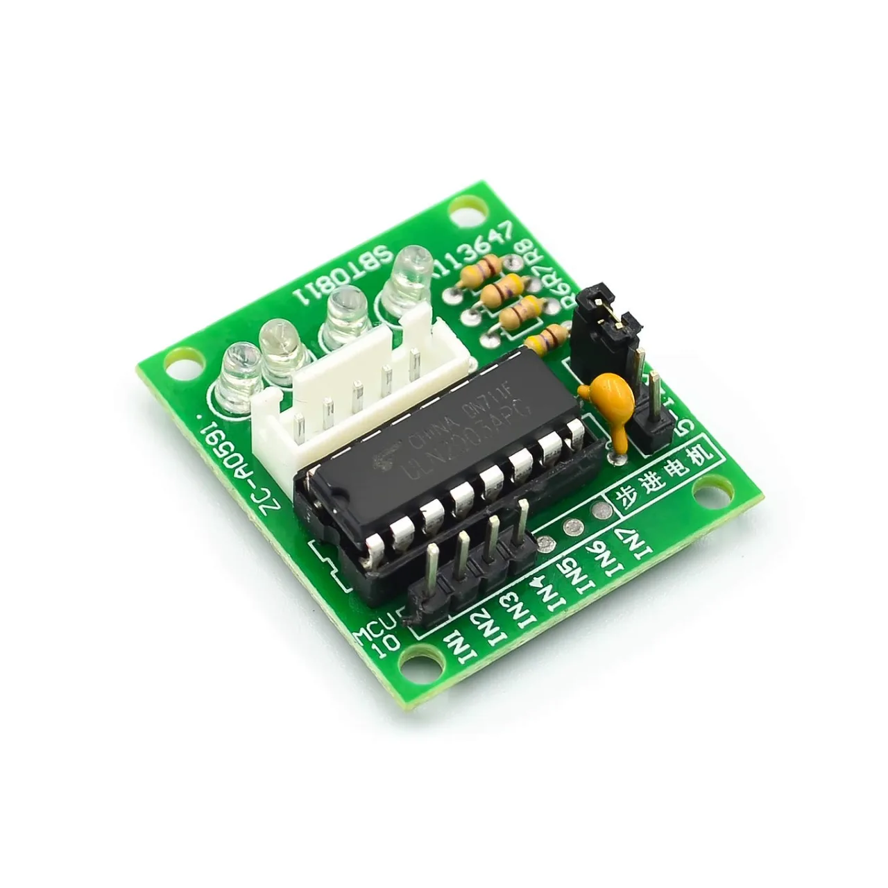
💻 Kod Açıklaması
Bu kod kurulumu, düğmenin durumunu sürekli kontrol eder ve düğmeye basılı kaldığı sürece motoru her seferinde bir adım hareket ettirir.
-
Kütüphane ve Pinleri Başlatma:
#include <Stepper.h>
const int stepsPerRevolution = 2048;
Stepper myStepper(stepsPerRevolution, 8, 10, 9, 11);
const int buttonPin = 2;-
Kurulum Fonksiyonu:
void setup() {
  myStepper.setSpeed(10);
  pinMode(buttonPin, INPUT_PULLUP);
  Serial.begin(9600);
}-
Sürekli Hareketli Döngü Fonksiyonu:
void loop() {
  if (digitalRead(buttonPin) == LOW) {
    myStepper.step(1); // Her seferinde bir adım
  }
}-
Motor, düğmeye basılı tutulduğu sürece her döngüde bir adım hareket eder.
-
Düğmeyi bırakmak hareketi anında durdurur.
Bu, adım adım veya yumuşak sürekli hareket için ince ayarlı manuel kontrol sağlar.
🎬 Tam Videodan Zaman Damgaları
Bu proje için videonun aşağıdaki bölümlerine bakın:
-
41:07 – Proje 4: Giriş
-
42:29 – Proje 4: Bağlantı
-
45:31 – Proje 4: Kod
-
49:38 – Proje 4: Gösterim
📁 İndirme Bölümü
Bu proje için eksiksiz kod ve bağlantı şemalarını aşağıda bulacaksınız. Bu tasarım, özellikle manuel makine jogging veya sürekli besleme uygulamaları için kullanışlıdır.
Sıradaki [Proje 5: STPB-3 ile Tetiklenen Bir Tam Devir].
Görseller
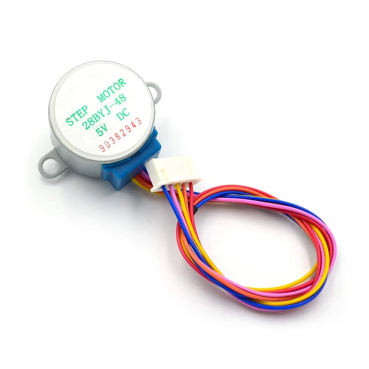
Bu eğitim şunun parçasıdır: Ders 107 28BYJ-48 Stepper 8 Projeleri
- Ders 107-1: 28BYJ-48 Step Motorunu Kodda Yön Belirlenmiş Şekilde Başlat ve Durdur
- Ders 107-2: 28BYJ-48 Step Motorunu Seri Monitör Üzerinden Kontrol Etme
- Ders 107-3: 28BYJ-48 Step Motorunun Üç Buton Kullanılarak Kontrol Edilmesi: CW, CCW ve Durdurma (STPB-1)
- Ders 107-5: 28BYJ-48 Motorunu CW veya CCW Yönünde Bir Devir İçin Gönderin, STPB-3
- Ders 107-6: Üç Buton Kullanarak 28BYJ-48 Step Motorunu Kontrol Etme, Açı ve Hız ile STPB-4
- Ders 107-7: 28BYJ-48 Step Motorunu Tanımlı STPB-5 Butonları ile Herhangi Bir Açıya Gönderme
- Ders 107-8: Bir 28BYJ-48 Step Motorunun Hızını Potansiyometre Kullanarak Kontrol Etme
/*
* Lesson 107-4: Controlling a stepper motor using 2 push buttons STPB-2.
STPB-2: We control a stepper motor using two push buttons. One push button rotates the motor clockwise (CW), and the other rotates it counter-clockwise (CCW). Keys must be kept pressed.

In this lesson, we learn how to use a mini stepper motor 28BYJ-48 for our project. I am presenting 8 projects so you can use it in almost any application. In the video, I have explained the code, shown the full wiring diagram, and shown how to connect the wires, push buttons, and breadboard.

  Project 1: Running motor
  Project 2: Controlling stepper motor from Serial Monitor
  Project 3: Controlling stepper motor using push button STPB-1
  Project 4: Controlling using push button STPB-2 keep pressing (this code)
  Project 5: One Revolution using push button STPB-3
  Project 6: Push button: Any Angle and speed STPB-4
  Project 7: Using multiple buttons for any angle: STPB-5 (angle, speed and direction)
  Project 8: Controlling stepper motor using potentiometer

  * Watch Video instruction for this code: https://youtu.be/TQ7R2bY-MWU
  *
  * This code is part of the Arduino Step by Step Course, which starts here:  https://youtu.be/-6qSrDUA5a8
  *
  * For the library for this code, visit http://robojax.com/
  *

If you found this tutorial helpful, please support me so I can continue creating
content like this. Make a donation using PayPal or a credit card: https://bit.ly/donate-robojax

* Written by Ahmad Shamshiri for Robojax Robojax.com
* on Feb 20, 2019 at 19:34 in Ajax, Ontario, Canada

  *  * This code is "AS IS" without warranty or liability. Free to be used as long as you keep this note intact.*
  * This code has been downloaded from Robojax.com
     This program is free software: you can redistribute it and/or modify
     it under the terms of the GNU General Public License as published by
     the Free Software Foundation, either version 3 of the License, or
     (at your option) any later version.

     This program is distributed in the hope that it will be useful,
     but WITHOUT ANY WARRANTY; without even the implied warranty of
     MERCHANTABILITY or FITNESS FOR A PARTICULAR PURPOSE.  See the
     GNU General Public License for more details.

     You should have received a copy of the GNU General Public License
     along with this program.  If not, see <https://www.gnu.org/licenses/>.

*/
int Pin1 = 10;//IN1 is connected to 10
int Pin2 = 11;//IN2 is connected to 11
int Pin3 = 12;//IN3 is connected to 12
int Pin4 = 13;//IN4 is connected to 13
int switchCW  =2;//define input pin for CW push button
int switchCCW =3;//define input pin for CCW push button


int pole1[] ={0,0,0,0, 0,1,1,1, 0};//pole1, 8 step values
int pole2[] ={0,0,0,1, 1,1,0,0, 0};//pole2, 8 step values
int pole3[] ={0,1,1,1, 0,0,0,0, 0};//pole3, 8 step values
int pole4[] ={1,1,0,0, 0,0,0,1, 0};//pole4, 8 step values


int poleStep = 0;
int  dirStatus = 3;// stores direction status 3= stop (do not change)

void setup()
{
 pinMode(Pin1, OUTPUT);//define pin for ULN2003 in1
 pinMode(Pin2, OUTPUT);//define pin for ULN2003 in2
 pinMode(Pin3, OUTPUT);//define pin for ULN2003 in3
 pinMode(Pin4, OUTPUT);//define pin for ULN2003 in4

 pinMode(switchCW,INPUT_PULLUP);
 pinMode(switchCCW,INPUT_PULLUP);

}
void loop()
{

  if(digitalRead(switchCCW) == LOW)
  {
    dirStatus =1;
  }else if(digitalRead(switchCW) == LOW)
  {
   dirStatus  = 2;
  }else
  {
    dirStatus =3;
  }
 if(dirStatus ==1){
   poleStep++;
    driveStepper(poleStep);
 }else if(dirStatus ==2){
   poleStep--;
    driveStepper(poleStep);
 }else{
  driveStepper(8);
 }
 if(poleStep>7){
   poleStep=0;
 }
 if(poleStep<0){
   poleStep=7;
 }
 delay(1);

}// loop


/*
 * @brief sends signal to the motor
 * @param "c" is an integer representing the pole of the motor
 * @return does not return anything
 *
 * www.Robojax.com code June 2019
 */
void driveStepper(int c)
{
     digitalWrite(Pin1, pole1[c]);
     digitalWrite(Pin2, pole2[c]);
     digitalWrite(Pin3, pole3[c]);
     digitalWrite(Pin4, pole4[c]);
}//driveStepper end here
İhtiyacın olabileceğini düşünüyor
-
Amazon
-
Amazon
-
AliExpressPurchase 5 pcs 28BYJ-48 stepper motors from AliExpresss.click.aliexpress.com
Kaynaklar ve referanslar
Dosyalar📁
Fritzing Dosyası
-
28BYJ-48 Stepper Motor
28BYJ-48 Stepper Motor.fzpz0.01 MB