Ce tutoriel fait partie de: Leçon 107 28BYJ-48 Stepper 8 Projets
Cette vidéo présente 8 projets. Chaque projet possède son propre code. Vous trouverez des liens vers d'autres vidéos ci-dessous.
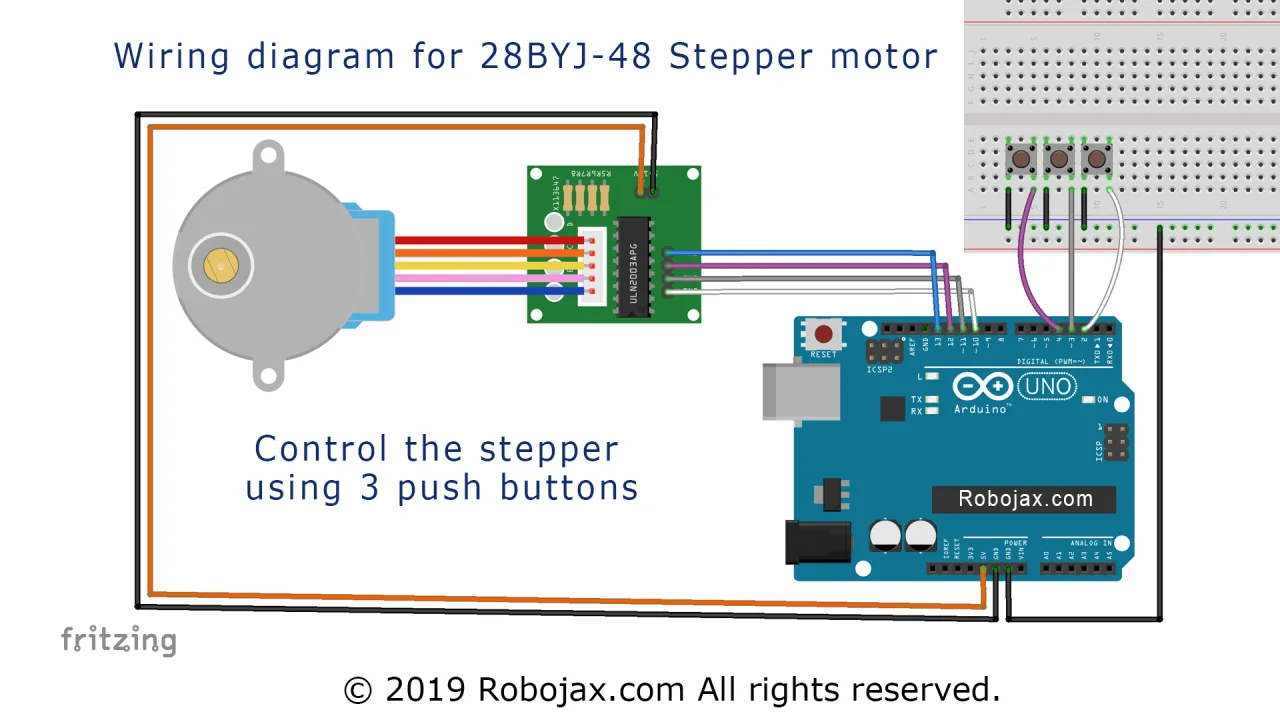
Leçon 107-3 : Contrôle d'un moteur pas à pas 28BYJ-48 à l'aide de trois boutons poussoirs : CW, CCW et Stop (STPB-1)
Projet 3 : Contrôle d'un moteur pas à pas à l'aide du bouton poussoir STPB-1 – Moteur pas à pas 28BYJ-48
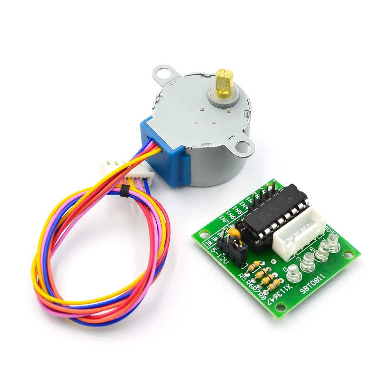
Cet article fait partie de la série de tutoriels de 8 projets démontrant comment contrôler le moteur pas à pas 28BYJ-48 avec Arduino. Dans le Projet 3, nous introduisons le premier contrôle basé sur un bouton poussoir utilisant un bouton momentané étiqueté STPB-1. Le bouton est utilisé pour déclencher la rotation du moteur avec une seule pression.
Tout le code source et le schéma de câblage pour ce projet se trouvent sous l'article.
📘 Introduction
Ce projet s'appuie sur les précédents en intégrant une entrée physique via un bouton poussoir. Lorsque l'utilisateur appuie une fois sur le bouton, le moteur effectue une révolution complète. Cette technique est essentielle dans les scénarios nécessitant une activation manuelle d'un processus de mouvement, comme déplacer une plateforme, alimenter un composant ou faire avancer un étage mécanique.
⚙️ Schéma de câblage
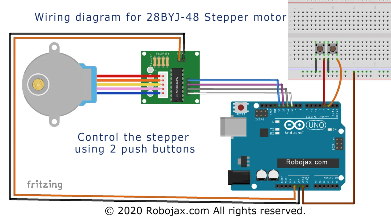
En plus du câblage du ULN2003 et du moteur pas à pas des Projets 1 et 2, la nouvelle connexion suivante est ajoutée :
-
Une borne du bouton poussoir (STPB-1) se connecte à la broche 2 de l'Arduino
-
L'autre borne se connecte à la masse (GND)
-
Une résistance de rappel au niveau haut (pull-up) est configurée en interne dans le code
Légende : Schéma de câblage montrant le contrôle du moteur via ULN2003 et l'entrée du bouton poussoir STPB-1 sur la broche 2.
💻 Explication du code
Le code utilise une entrée numérique pour détecter une pression sur le bouton et déclencher le mouvement du moteur :
-
Configuration du moteur pas à pas et des broches :
#include <Stepper.h>
const int stepsPerRevolution = 2048;
Stepper myStepper(stepsPerRevolution, 8, 10, 9, 11);
const int buttonPin = 2;-
Fonction Setup :
void setup() {
  myStepper.setSpeed(10);
  pinMode(buttonPin, INPUT_PULLUP);
  Serial.begin(9600);
}-
Utilise
INPUT_PULLUPpour simplifier le câblage (aucune résistance externe nécessaire).
-
Fonction Loop :
void loop() {
  if (digitalRead(buttonPin) == LOW) {
    myStepper.step(stepsPerRevolution);
    delay(1000); // Empêche un double déclenchement accidentel
  }
}-
Détecte une pression sur le bouton (état LOW en raison de la logique pull-up)
-
Fait tourner le moteur d'une révolution complète vers l'avant à chaque pression
🎬 Horodatages de la vidéo complète
Pour regarder ce projet dans la vidéo du tutoriel, utilisez les horodatages ci-dessous :
-
35:48 – Projet 3 : Explication du câblage
-
37:45 – Projet 3 : Explication du code
-
39:59 – Projet 3 : Démonstration
📁 Section de téléchargement
Vous trouverez le code source et le schéma de câblage pour ce projet sous l'article. Cette configuration est un excellent point de départ pour déclencher un mouvement dans des applications contrôlées par l'utilisateur.
Le prochain est le [Projet 4 : Bouton poussoir STPB-2 – Mode maintien pour exécution].
Images
Ce tutoriel fait partie de: Leçon 107 28BYJ-48 Stepper 8 Projets
- Leçon 107-1 : Démarrer et arrêter le moteur pas à pas 28BYJ-48 avec la direction définie dans le code
- Leçon 107-2 : Contrôler un moteur pas à pas 28BYJ-48 via le moniteur série
- Leçon 107-4 : Contrôle d'un moteur pas à pas 28BYJ-48 à l'aide de deux boutons poussoirs, CW, CCW (maintenir enfoncé), STPB-2
- Leçon 107-5 : Envoyer le moteur 28BYJ-48 pour une révolution dans le sens horaire ou antihoraire, STPB-3
- Leçon 107-6 : Contrôle d'un moteur pas à pas 28BYJ-48 à l'aide de trois boutons poussoirs, avec angle et vitesse STPB-4
- Leçon 107-7 : Envoyer un moteur pas à pas 28BYJ-48 à n'importe quel angle avec des boutons poussoirs STPB-5 définis
- Leçon 107-8 : Contrôle de la vitesse d’un moteur pas à pas 28BYJ-48 à l’aide d’un potentiomètre
++
/*
* Lesson 107-3: Controlling a stepper motor using 3 push buttons.
We have 3 push buttons: one for clockwise (CW), the second for counter-clockwise (CCW), and one for stopping the motor.

In this lesson, we learn how to use a mini stepper motor 28BYJ-48 for our project. I am presenting 8 projects
  so you can use it in almost any application. In the video, I have explained the code, shown the full wiring diagram, and
  how to connect the wires, push buttons, and breadboard.

  Project 1: Running motor
  Project 2: Controlling stepper motor from Serial Monitor
  Project 3: Controlling stepper motor using push button STPB-1 (this code)
  Project 4: Controlling using push button STPB-2  keep pressing
  Project 5: One Revolution using push button STPB-3
  Project 6: Push button: Any Angle and speed STPB-4
  Project 7: Using multiple buttons to control any angle: STPB-5 angle, speed and direction
  Project 8: Controlling stepper motor using potentiometer

  * Watch Video instruction for this code: https://youtu.be/TQ7R2bY-MWU
  *
  * This code is part of the Arduino Step by Step Course, which starts here:  https://youtu.be/-6qSrDUA5a8
  *
  * For the library for this code, visit http://robojax.com/
  *
 If you found this tutorial helpful, please support me so I can continue creating
 content like this. Make a donation using PayPal via credit card: https://bit.ly/donate-robojax

 * Written by Ahmad Shamshiri for Robojax Robojax.com
 * on Feb 20, 2019 at 19:34 in Ajax, Ontario, Canada

  *  * This code is "AS IS" without warranty or liability. Free to be used as long as you keep this note intact.*
  * This code has been downloaded from Robojax.com
     This program is free software: you can redistribute it and/or modify
     it under the terms of the GNU General Public License as published by
     the Free Software Foundation, either version 3 of the License, or
     (at your option) any later version.

     This program is distributed in the hope that it will be useful,
     but WITHOUT ANY WARRANTY; without even the implied warranty of
     MERCHANTABILITY or FITNESS FOR A PARTICULAR PURPOSE.  See the
     GNU General Public License for more details.

     You should have received a copy of the GNU General Public License
     along with this program.  If not, see <https://www.gnu.org/licenses/>.

 */

int Pin1 = 10;//IN1 is connected to 10
int Pin2 = 11;//IN2 is connected to 11
int Pin3 = 12;//IN3 is connected to 12
int Pin4 = 13;//IN4 is connected to 13
int switchCW  =2;//define input pin for CW push button
int switchStop=3;//define input pin for Stop push button
int switchCCW =4;//define input pin for CCW push button

int pole1[] ={0,0,0,0, 0,1,1,1, 0};//pole1, 8 step values
int pole2[] ={0,0,0,1, 1,1,0,0, 0};//pole2, 8 step values
int pole3[] ={0,1,1,1, 0,0,0,0, 0};//pole3, 8 step values
int pole4[] ={1,1,0,0, 0,0,0,1, 0};//pole4, 8 step values


int poleStep = 0;
int  dirStatus = 3;// stores direction status 3= stop (do not change)

void setup()
{
 pinMode(Pin1, OUTPUT);//define pin for ULN2003 in1
 pinMode(Pin2, OUTPUT);//define pin for ULN2003 in2
 pinMode(Pin3, OUTPUT);//define pin for ULN2003 in3
 pinMode(Pin4, OUTPUT);//define pin for ULN2003 in4

 pinMode(switchCW,INPUT_PULLUP);// CW push button pin as input
 pinMode(switchStop,INPUT_PULLUP);//Stop push button pin as input
 pinMode(switchCCW,INPUT_PULLUP);//CCW push button pin as input

}
void loop()
{

  if(digitalRead(switchCCW) == LOW)
  {
    dirStatus =1;
  }else if(digitalRead(switchCW) == LOW)
  {
   dirStatus  = 2;
  }else if(digitalRead(switchStop) == LOW)
  {
    dirStatus =3;
  }
 if(dirStatus ==1){
   poleStep++;
    driveStepper(poleStep);
 }else if(dirStatus ==2){
   poleStep--;
    driveStepper(poleStep);
 }else{
  driveStepper(8);
 }
 if(poleStep>7){
   poleStep=0;
 }
 if(poleStep<0){
   poleStep=7;
 }
 delay(1);

}// loop

void driveStepper(int c)
{
     digitalWrite(Pin1, pole1[c]);
     digitalWrite(Pin2, pole2[c]);
     digitalWrite(Pin3, pole3[c]);
     digitalWrite(Pin4, pole4[c]);
}
Ce dont vous pourriez avoir besoin
-
Amazon
-
Amazon
-
AliExpressAchetez 5 pcs de moteurs pas à pas 28BYJ-48 sur AliExpress.s.click.aliexpress.com
Ressources et références
-
Externe
-
Externe
-
Externe
Fichiers📁
Fichier Fritzing
-
28BYJ-48 Stepper Motor
28BYJ-48 Stepper Motor.fzpz0.01 MB