ULN2003 드라이버와 아두이노를 사용한 28BYJ-48 스테퍼 모터
이 튜토리얼에서는 Arduino를 사용하여 ULN2003 드라이버로 28BYJ-48 스테퍼 모터를 제어하는 방법을 배울 것입니다. 이 설정은 모터의 위치와 속도를 정밀하게 제어할 수 있게 해줍니다. 이 프로젝트가 끝나면 모터를 양 방향으로 회전시키고 효과적으로 스텝을 제어할 수 있게 될 것입니다.
우리는 저렴한 비용과 사용의 용이성 덕분에 다양한 로봇 및 자동화 프로젝트에 널리 사용되는 28BYJ-48 스테퍼 모터를 사용할 것입니다. ULN2003 드라이버 보드는 스테퍼 모터와 아두이노를 연결하여 모터의 움직임을 제어하는 스텝 신호를 보낼 수 있게 해줍니다. 이 튜토리얼은 모터를 회전시키기 위한 필요한 배선과 코드를 안내할 것입니다.
추가적인 설명을 원하시면 이 튜토리얼과 관련된 비디오를 참조하시기 바랍니다 (비디오 0:45에서).
하드웨어 설명
이 프로젝트의 주요 구성 요소는 28BYJ-48 스테퍼 모터와 ULN2003 드라이버 보드입니다. 스테퍼 모터는 특정 순서로 전원을 공급하여 회전을 생성할 수 있는 여러 코일로 구성되어 있습니다. ULN2003 드라이버는 스위치 역할을 하여 아두이노가 각 코일에 공급되는 전력을 제어할 수 있도록 합니다.
ULN2003 드라이버는 스테퍼 모터에 필요한 더 높은 전류를 처리하기 위해 다를링턴 트랜지스터 배열을 사용합니다. Arduino의 핀에서 HIGH 신호가 출력되면, 모터의 해당 코일로 전류가 흐르게 되어 모터가 움직입니다. 이를 통해 모터의 회전 각도와 속도를 정밀하게 제어할 수 있습니다.
데이터시트 세부정보
| 제조업체 | ULN2003 |
|---|---|
| 부품 번호 | ULN2003 |
| 로직/입출력 전압 | 5 V |
| 공급 전압 | 5-30 V (최대) |
| 출력 전류 (채널당) | 최대 500 mA |
| 채널당 피크 전류 | 2 A 맥스 |
| PWM 주파수 안내 | N/A |
| 입력 논리 임계값 | 0.8 V (낮음), 2.4 V (높음) |
| 전압 강하 / RDS(온)/ 포화 | 1.5 V 최대 |
| 열적 한계 | 70 °C 최대 |
| 패키지 | DIP-16 |
| 노트 / 변형 | 5V 스테퍼 모터와 일반적으로 사용됩니다. |
- 드라이버가 귀하의 모터에 대한 현재 요구 사항을 처리할 수 있는지 확인하십시오.
- 필요한 경우 열 제한을 관리하기 위해 히트 싱크를 사용하십시오.
- 모든 연결이 안전한지 확인하여 부유 입력을 피하십시오.
- 간단한 단계 시퀀스를 실행하여 모터를 테스트한 후 더 큰 프로젝트에 통합하세요.
- 모터에 적절한 공급 전압으로 전원을 공급해야 합니다.
배선 지침
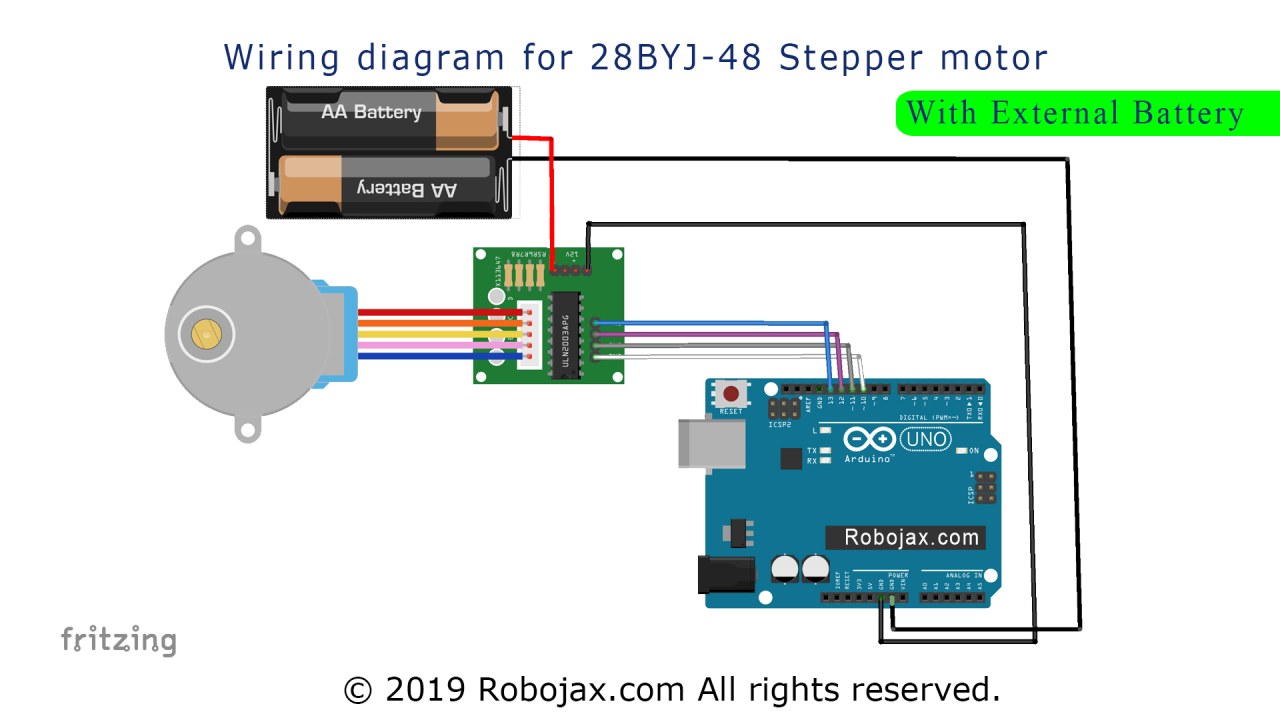
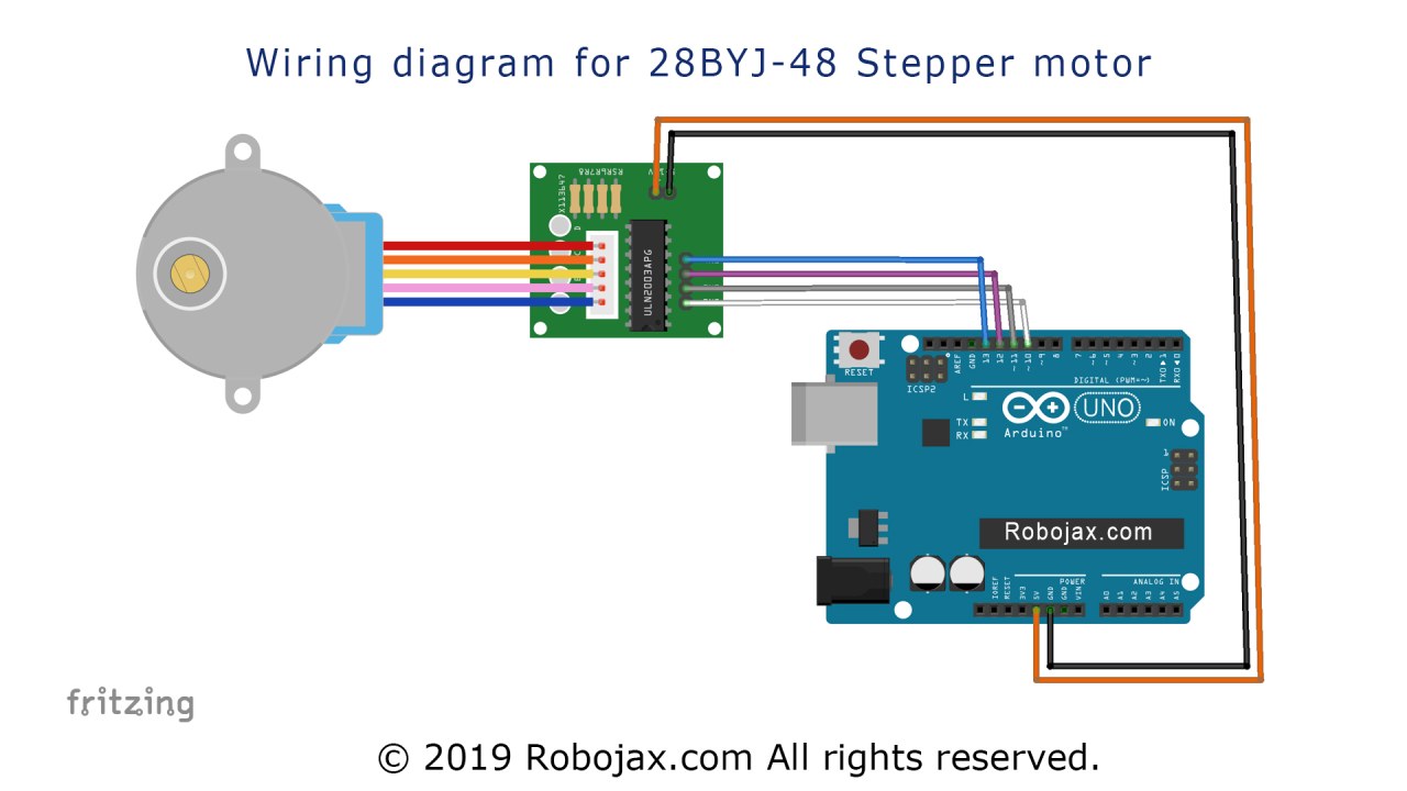
28BYJ-48 스테퍼 모터를 ULN2003 드라이버와 아두이노에 연결하려면 다음 단계를 따르세요:
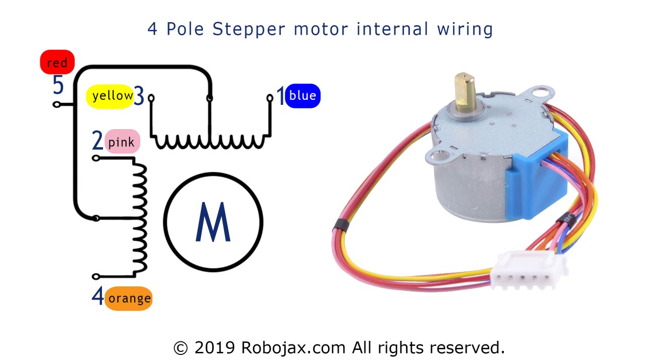
먼저 모터를 ULN2003 드라이버에 연결합니다. 모터에는 일반적으로 주황색, 노란색, 분홍색, 파란색으로 색상 코드가 지정된 네 개의 전선이 있습니다. 이 전선들을 ULN2003 드라이버의 해당 출력 핀에 연결합니다. 연결은 다음과 같습니다:
Orange전선으로OUT1Yellow전선으로OUT2Pink전선으로OUT3Blue전선으로OUT4
다음으로, ULN2003 드라이버를 아두이노에 연결합니다. 드라이버의 입력 핀은 아두이노의 네 개 디지털 핀에 해당합니다. 예를 들어:
IN1로Pin 10IN2로Pin 11IN3로Pin 12IN4로Pin 13
마지막으로, ULN2003 드라이버의 전원 및 접지 핀을 아두이노에 연결합니다. 연결하십시오.VCC아두이노의 5V 출력에 핀을 연결하고GND아두이노의 접지에 핀을 연결하세요. 시스템의 전원을 켜기 전에 모든 연결이 안전한지 확인하세요.
코드 예제 및 안내
Arduino 코드의 설정 섹션에서 ULN2003 드라이버에 연결된 핀을 정의합니다:
int Pin1 = 10;
int Pin2 = 11;
int Pin3 = 12;
int Pin4 = 13;
여기, 우리는 네 개의 정수 변수를 선언합니다:Pin1,Pin2,Pin3, andPin4아두이노의 디지털 핀에 해당합니다. 이 핀들은 스테퍼 모터의 움직임을 제어합니다.
안에setup()이 함수에서 우리는 이 핀들을 출력으로 설정합니다:
void setup() {
 pinMode(Pin1, OUTPUT);
 pinMode(Pin2, OUTPUT);
 pinMode(Pin3, OUTPUT);
 pinMode(Pin4, OUTPUT);
}
이 설정은 Arduino가 ULN2003 드라이버에 신호를 보내 모터를 제어할 수 있도록 보장합니다.pinMode함수는 각 핀을 OUTPUT 모드로 설정하여 신호를 보낼 수 있도록 합니다.
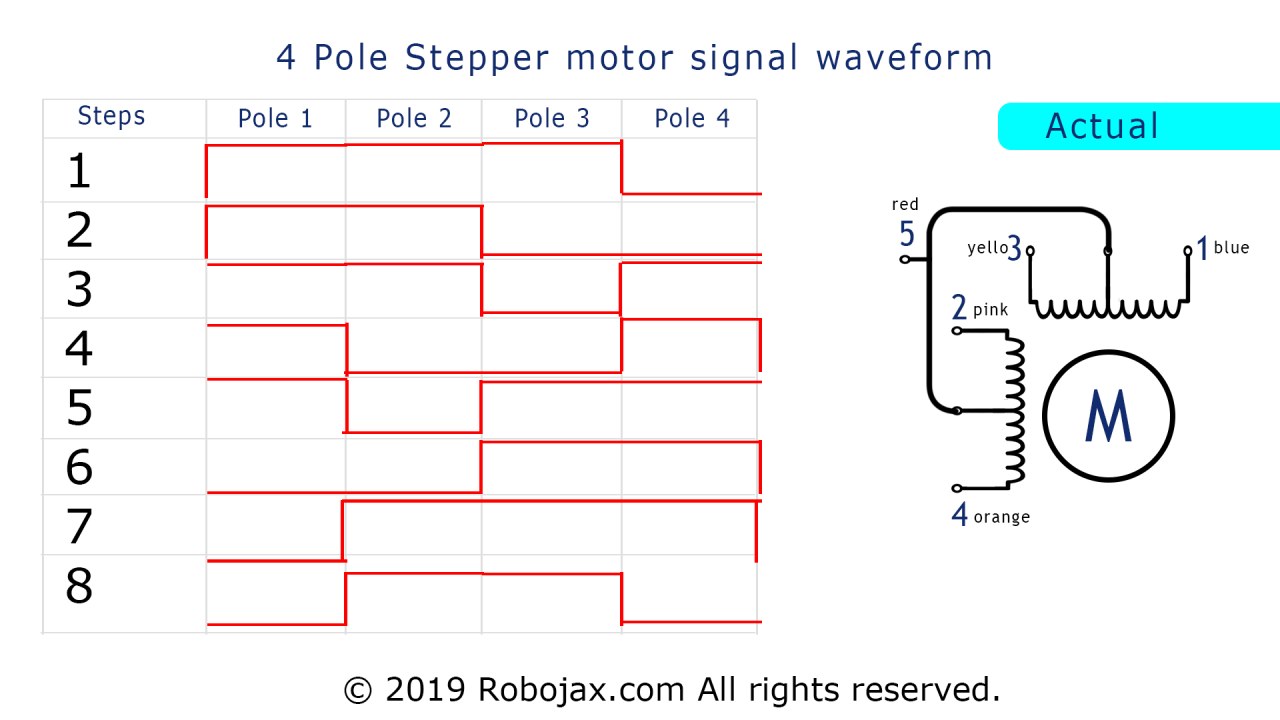
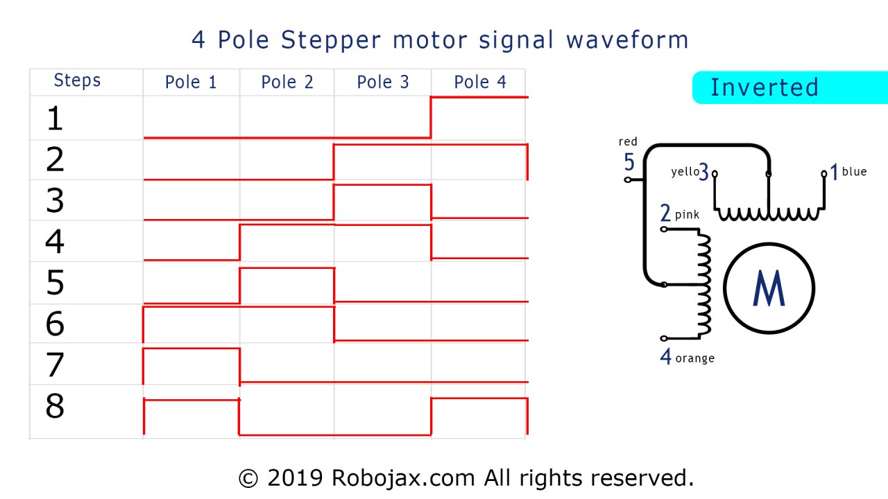
마지막으로, 메인 루프에서 변수를 기반으로 모터의 스텝을 제어하기 위해 스위치 케이스를 생성합니다._step:
switch(_step){
   case 0:
     digitalWrite(Pin1, LOW);
     digitalWrite(Pin2, LOW);
     digitalWrite(Pin3, LOW);
     digitalWrite(Pin4, HIGH);
   break;
   // Additional cases follow
}
이 발췌에서 우리는 사용합니다digitalWrite각 핀에 현재에 따라 HIGH 또는 LOW 신호를 보내기 위해_step이것은 어떤 코일이 전 energized 되는지를 제어하여 모터가 회전할 수 있도록 합니다. 이러한 코드 조각을 통합한 전체 코드는 기사 아래에 로드될 것입니다.
시연 / 기대할 사항
모든 것이 올바르게 연결되고 코드가 업로드되면 스테퍼 모터는 아두이노의 신호에 따라 회전해야 합니다. 루프의 지연 시간을 수정하거나 스텝을 변경하여 모터가 어떻게 반응하는지 테스트할 수 있습니다. 모터에 전원이 제대로 공급되지 않으면 움직이지 않거나 불규칙하게 동작할 수 있으니 주의하세요.
장들
- 소개 - 0:00
- 하드웨어 설명 - 1:30
- 배선 지침 - 3:15
- 코드 예제 및 워크스루 - 5:00
- 시연 / 기대할 사항 - 7:45
이미지
// Original source is http://www.geeetech.com/wiki/index.php/Stepper_Motor_5V_4-Phase_5-Wire_%26_ULN2003_Driver_Board_for_Arduino
// Update by Ahmad Shamshiri for RoboJax.com
// Published on March 27, 2017 in Ajax, ON, Canada.
/*
 *
  Need wiring diagram from this code:  https://youtu.be/0glBk917HPg
  Purchase My Arduino course on Udemy.com http://robojax.com/L/?id=62
 *

 * Get this code and other Arduino codes from RoboJax.com
Learn Arduino step by step in a structured course with all material, wiring diagrams, and libraries
all in one place. Purchase My course on Udemy.com http://robojax.com/L/?id=62

If you found this tutorial helpful, please support me so I can continue creating
content like this.

or make a donation using PayPal http://robojax.com/L/?id=64

 *  * This code is "AS IS" without warranty or liability. Free to be used as long as you keep this note intact.*
 * This code has been downloaded from RoboJax.com
    This program is free software: you can redistribute it and/or modify
    it under the terms of the GNU General Public License as published by
    the Free Software Foundation, either version 3 of the License, or
    (at your option) any later version.

    This program is distributed in the hope that it will be useful,
    but WITHOUT ANY WARRANTY; without even the implied warranty of
    MERCHANTABILITY or FITNESS FOR A PARTICULAR PURPOSE.  See the
    GNU General Public License for more details.

    You should have received a copy of the GNU General Public License
    along with this program.  If not, see <https://www.gnu.org/licenses/>.
 */


int Pin1 = 10;
int Pin2 = 11;
int Pin3 = 12;
int Pin4 = 13;
int _step = 0;
boolean dir = true;// false=clockwise, true=counter clockwise
int count=0;
void setup()
{
 pinMode(Pin1, OUTPUT);
 pinMode(Pin2, OUTPUT);
 pinMode(Pin3, OUTPUT);
 pinMode(Pin4, OUTPUT);
}
 void loop()
{
 switch(_step){
   case 0:
     digitalWrite(Pin1, LOW);
     digitalWrite(Pin2, LOW);
     digitalWrite(Pin3, LOW);
     digitalWrite(Pin4, HIGH);
   break;
   case 1:
     digitalWrite(Pin1, LOW);
     digitalWrite(Pin2, LOW);
     digitalWrite(Pin3, HIGH);
     digitalWrite(Pin4, HIGH);
   break;
   case 2:
     digitalWrite(Pin1, LOW);
     digitalWrite(Pin2, LOW);
     digitalWrite(Pin3, HIGH);
     digitalWrite(Pin4, LOW);
   break;
   case 3:
     digitalWrite(Pin1, LOW);
     digitalWrite(Pin2, HIGH);
     digitalWrite(Pin3, HIGH);
     digitalWrite(Pin4, LOW);
   break;
   case 4:
     digitalWrite(Pin1, LOW);
     digitalWrite(Pin2, HIGH);
     digitalWrite(Pin3, LOW);
     digitalWrite(Pin4, LOW);
   break;
   case 5:
     digitalWrite(Pin1, HIGH);
     digitalWrite(Pin2, HIGH);
     digitalWrite(Pin3, LOW);
     digitalWrite(Pin4, LOW);
   break;
     case 6:
     digitalWrite(Pin1, HIGH);
     digitalWrite(Pin2, LOW);
     digitalWrite(Pin3, LOW);
     digitalWrite(Pin4, LOW);
   break;
   case 7:
     digitalWrite(Pin1, HIGH);
     digitalWrite(Pin2, LOW);
     digitalWrite(Pin3, LOW);
     digitalWrite(Pin4, HIGH);
   break;
   default:
     digitalWrite(Pin1, LOW);
     digitalWrite(Pin2, LOW);
     digitalWrite(Pin3, LOW);
     digitalWrite(Pin4, LOW);
   break;
 }
 if(dir){
   _step++;
 }else{
   _step--;
 }
 if(_step>7){
   _step=0;
 }
 if(_step<0){
   _step=7;
 }
 delay(1);

}
필요할 수 있는 것들
-
아마존
-
알리익스프레스Purchase 5 pcs 28BYJ-48 stepper motors from AliExpresss.click.aliexpress.com
-
알리익스프레스
자원 및 참고자료
-
외부
-
외부
-
외부
파일📁
파일이 없습니다.