Using Two or More VL6180X 20cm Time-of-Flight Proximity Sensors with Arduino
In this tutorial, we will explore how to use two or more VL6180X time-of-flight proximity sensors with an Arduino. These sensors are capable of measuring distances up to 20 centimeters, making them ideal for various robotics applications. By the end of this guide, you will understand how to wire the sensors correctly and implement the code needed to read distance measurements from each sensor.

The VL6180X sensors utilize I2C communication, allowing multiple sensors to be connected to the same bus. This tutorial will cover both single and dual sensor setups, with an emphasis on how to manage multiple sensors effectively. If you need further clarification, be sure to check the video (in video at 00:00).
Hardware Explained
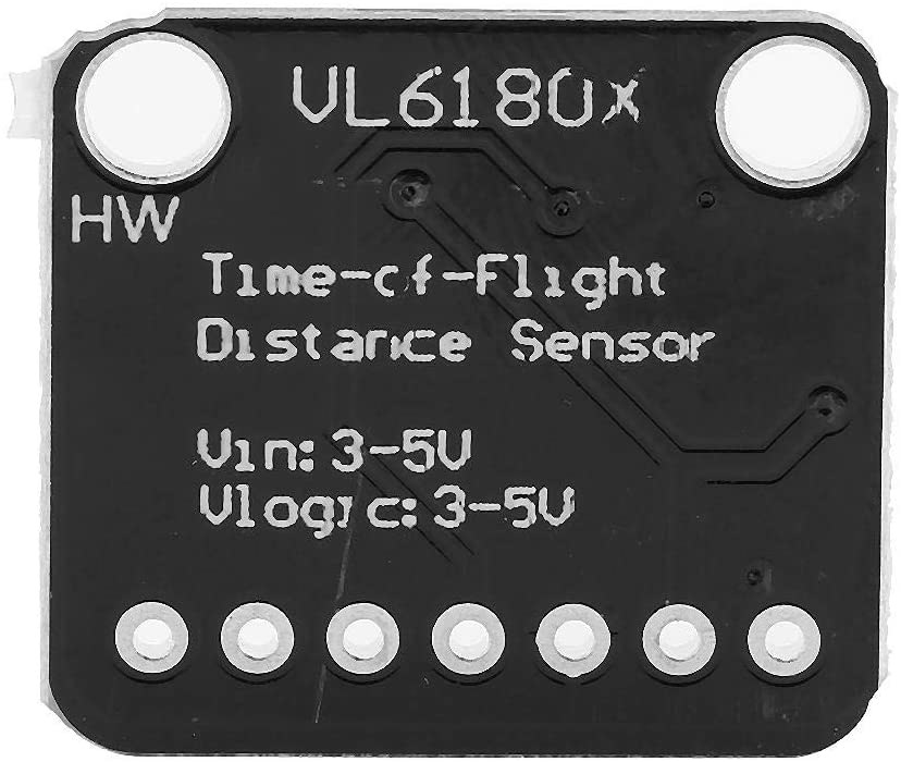
The key component of this project is the VL6180X proximity sensor. This compact sensor is designed for short-range distance measurement and operates within a voltage range of 2.6 to 3.6 volts. It utilizes a laser-assisted time-of-flight measurement technique, allowing for accurate readings with minimal power consumption.
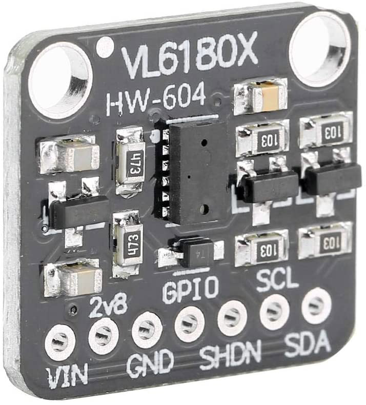
Each sensor has several pins, including GPIO for shutdown, SCL and SDA for I2C communication, and a ground pin. When using multiple sensors, it's essential to manage their shutdown pins to avoid conflicts in I2C addresses, as each sensor must have a unique address on the bus.
Datasheet Details
| Manufacturer | STMicroelectronics |
|---|---|
| Part number | VL6180X |
| Logic/IO voltage | 2.6 – 3.6 V |
| Supply voltage | 2.6 – 3.6 V |
| Output current (per channel) | 1.7 mA (typ.) |
| Peak current (per channel) | … |
| PWM frequency guidance | … |
| Input logic thresholds | … |
| Voltage drop / RDS(on) / saturation | … |
| Thermal limits | -20 to 70 °C |
| Package | 4.8 x 2.8 x 1 mm |
| Notes / variants | Maximum range 62 cm |
- Ensure proper power supply within the specified voltage range.
- Use unique I2C addresses for each sensor to avoid communication conflicts.
- Manage the shutdown pins to power on/off sensors as needed.
- Utilize pull-up resistors on I2C lines, if necessary, for stable communication.
- Be mindful of the operating temperature limits to avoid sensor damage.
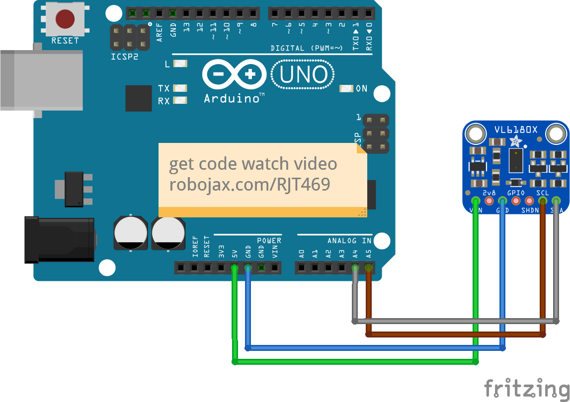
Wiring Instructions

To wire the VL6180X sensors to an Arduino, start by connecting the power and ground. Connect the sensor's 5V pin to the 5V pin on the Arduino, and the GND pin to the Arduino's ground. Next, connect the SCL pin of the sensor to the Arduino's A5 pin, and the SDA pin to the A4 pin. If you're using two sensors, connect the shutdown pins of the first sensor to 7 and the second sensor to 6.
For multiple sensors, ensure that each sensor's shutdown pins are controlled independently to manage I2C addresses easily. You can connect the first sensor's XSHUT pin to 7 and the second sensor's XSHUT pin to 6. This setup will allow you to initialize each sensor one at a time. Remember to leave a space between the sensors on the breadboard to prevent any short circuits.
Code Examples & Walkthrough
In the code, we begin by including the necessary library for the VL6180X sensor:
#include
This line imports the Adafruit library, which provides the necessary functions to interact with the sensor.
Next, we define the addresses and shutdown pins for our sensors:
#define LOX1_ADDRESS 0x30
#define LOX2_ADDRESS 0x31
#define SHT_LOX1 7
#define SHT_LOX2 6
Here, we set unique addresses for each sensor and specify the pins used to control their shutdown states.
In the setup() function, we initialize the sensors:
void setup() {
Serial.begin(115200);
pinMode(SHT_LOX1, OUTPUT);
pinMode(SHT_LOX2, OUTPUT);
setID();
}
This snippet initializes the serial communication and sets the shutdown pins as outputs. The setID() function is called to manage the sensor addresses and activate them accordingly.
Demonstration / What to Expect
During testing, you can expect accurate readings from the sensors within the specified range. When an object is placed within 20 centimeters, the sensor should provide consistent distance measurements (in video at 05:00). If the sensors are not configured correctly, you may experience errors or inaccurate readings.
As you run the code, each sensor's readings will be printed in the serial monitor. Make sure to check the readings against known distances to verify accuracy. If you notice any discrepancies, double-check your wiring and ensure that the sensors are powered correctly.
Video Timestamps
- 00:00 Start
- 00:56 Introduction
- 04:30 VL6080V Datasheet viewed
- 06:58 Wiring shown
- 07:32 Wiring for two or more sensors
- 09:22 Installing library
- 10:30 Arduino code explained (1 sensor)
- 12:57 Code for 2 or more sensors
- 19:35 Demonstration 1 sensor
- 22:05 Demonstration with 2 sensors
/*
* Arduino code
Using two or more VL6180X 20cm Time-of-Flight proximity sensors with Arduino
View code for using single VL6180X sensors: https://robojax.com?vid=robojax_VL6180X_laser
* Original code and library by https://github.com/adafruit/Adafruit_VL6180X
*
* Written/updated by Ahmad Shamshiri for Robojax Robojax.com
* on Mar 12, 2021 in Ajax, Ontario, Canada
Watch the video instruction for this sketch: https://youtu.be/_H9D0czQpSI
If you found this tutorial helpful, please support me so I can continue creating
content like this.
or make a donation using PayPal http://robojax.com/L/?id=64
*
* Code is available at http://robojax.com/learn/arduino
* This code is "AS IS" without warranty or liability. Free to be used as long as you keep this note intact.*
* This code has been downloaded from Robojax.com
This program is free software: you can redistribute it and/or modify
it under the terms of the GNU General Public License as published by
the Free Software Foundation, either version 3 of the License, or
(at your option) any later version.
This program is distributed in the hope that it will be useful,
but WITHOUT ANY WARRANTY; without even the implied warranty of
MERCHANTABILITY or FITNESS FOR A PARTICULAR PURPOSE. See the
GNU General Public License for more details.
You should have received a copy of the GNU General Public License
along with this program. If not, see <https://www.gnu.org/licenses/>.
*/
#include <Adafruit_VL6180X.h>
// address we will assign if dual sensor is present
#define LOX1_ADDRESS 0x30
#define LOX2_ADDRESS 0x31
// set the pins to shutdown
#define SHT_LOX1 7
#define SHT_LOX2 6
// Optional define GPIO pins to check to see if complete
#define GPIO_LOX1 4
#define GPIO_LOX2 3
#define TIMING_PIN 13
// objects for the VL6180X
Adafruit_VL6180X lox1 = Adafruit_VL6180X();
Adafruit_VL6180X lox2 = Adafruit_VL6180X();
// Setup mode for doing reads
typedef enum {RUN_MODE_DEFAULT, RUN_MODE_TIMED, RUN_MODE_ASYNC, RUN_MODE_GPIO, RUN_MODE_CONT} runmode_t;
runmode_t run_mode = RUN_MODE_DEFAULT;
uint8_t show_command_list = 1;
//==========================================================================
// Define some globals used in the continuous range mode
// Note: going to start table drive this part, may back up and do the rest later
Adafruit_VL6180X *sensors[] = {&lox1, &lox2};
const uint8_t COUNT_SENSORS = sizeof(sensors) / sizeof(sensors[0]);
const int sensor_gpios[COUNT_SENSORS] = {GPIO_LOX1, GPIO_LOX2}; // if any are < 0 will poll instead
uint8_t tempRange;
uint8_t sensor_ranges[COUNT_SENSORS];
uint8_t sensor_status[COUNT_SENSORS];
// Could do with uint8_t for 8 sensors, but just in case...
const uint16_t ALL_SENSORS_PENDING = ((1 << COUNT_SENSORS) - 1);
uint16_t sensors_pending = ALL_SENSORS_PENDING;
uint32_t sensor_last_cycle_time;
/*
Reset all sensors by setting all of their XSHUT pins low for delay(10), then set all XSHUT high to bring out of reset
Keep sensor #1 awake by keeping XSHUT pin high
Put all other sensors into shutdown by pulling XSHUT pins low
Initialize sensor #1 with lox.begin(new_i2c_address) Pick any number but 0x29 and it must be under 0x7F. Going with 0x30 to 0x3F is probably OK.
Keep sensor #1 awake, and now bring sensor #2 out of reset by setting its XSHUT pin high.
Initialize sensor #2 with lox.begin(new_i2c_address) Pick any number but 0x29 and whatever you set the first sensor to
*/
void setID() {
// all reset
digitalWrite(SHT_LOX1, LOW);
digitalWrite(SHT_LOX2, LOW);
delay(10);
// all unreset
digitalWrite(SHT_LOX1, HIGH);
digitalWrite(SHT_LOX2, HIGH);
delay(10);
// activating LOX1 and reseting LOX2
digitalWrite(SHT_LOX1, HIGH);
digitalWrite(SHT_LOX2, LOW);
// initing LOX1
if (!lox1.begin()) {
Serial.println(F("Failed to boot first VL6180X"));
while (1);
}
lox1.setAddress(LOX1_ADDRESS);
delay(10);
// activating LOX2
digitalWrite(SHT_LOX2, HIGH);
delay(10);
//initing LOX2
if (!lox2.begin()) {
Serial.println(F("Failed to boot second VL6180X"));
while (1);
}
lox2.setAddress(LOX2_ADDRESS);
delay(10);
}
void readSensor(Adafruit_VL6180X &vl) {
float lux = vl.readLux(VL6180X_ALS_GAIN_5);
uint8_t range = vl.readRange();
uint8_t status = vl.readRangeStatus();
if (status == VL6180X_ERROR_NONE) {
tempRange = range;//save it for the moment
}
// Some error occurred, print it out!
if ((status >= VL6180X_ERROR_SYSERR_1) && (status <= VL6180X_ERROR_SYSERR_5)) {
Serial.print("(System error)");
}
else if (status == VL6180X_ERROR_ECEFAIL) {
Serial.print("(ECE failure)");
}
else if (status == VL6180X_ERROR_NOCONVERGE) {
Serial.print("(No convergence)");
}
else if (status == VL6180X_ERROR_RANGEIGNORE) {
Serial.print("(Ignoring range)");
}
else if (status == VL6180X_ERROR_SNR) {
Serial.print("Signal/Noise error");
}
else if (status == VL6180X_ERROR_RAWUFLOW) {
Serial.print("Raw reading underflow");
}
else if (status == VL6180X_ERROR_RAWOFLOW) {
Serial.print("Raw reading overflow");
}
else if (status == VL6180X_ERROR_RANGEUFLOW) {
Serial.print("Range reading underflow");
}
else if (status == VL6180X_ERROR_RANGEOFLOW) {
Serial.print("Range reading overflow");
}
}
void read_sensors() {
readSensor(lox1);
sensor_ranges[0]=tempRange;//save it now
readSensor(lox2);
sensor_ranges[1]=tempRange; //save it now
Serial.println();
}
//===============================================================
// Setup
//===============================================================
void setup() {
Serial.begin(115200);
// wait until serial port opens for native USB devices
while (! Serial) {
delay(1);
}
pinMode(SHT_LOX1, OUTPUT);
pinMode(SHT_LOX2, OUTPUT);
// Enable timing pin so easy to see when pass starts and ends
pinMode(TIMING_PIN, OUTPUT);
#ifdef GPIO_LOX1
// If we defined GPIO pins, enable them as PULL UP
pinMode(GPIO_LOX1, INPUT_PULLUP);
pinMode(GPIO_LOX2, INPUT_PULLUP);
#endif
Serial.println("Shutdown pins inited...");
digitalWrite(SHT_LOX1, LOW);
digitalWrite(SHT_LOX2, LOW);
digitalWrite(TIMING_PIN, LOW);
Serial.println("All in reset mode...(pins are low)");
Serial.println("Starting...");
setID();
}
//===============================================================
// Loop
//===============================================================
void loop() {
read_sensors();
for(int i=0; i<COUNT_SENSORS; i++)
{
Serial.print("Sensor ");
Serial.print(i);
Serial.print(" :");
Serial.print(sensor_ranges[i]);
Serial.print("mm");
Serial.println();
}
// if(sensor_ranges[1] >=76)
// {
// //do something here
// }
delay(100);
}
/*
* Arduino code
* Lesson 76-2: Using two or more VL6180 Laser Distance Sensors with Arduino
* Adafruit code modified for this tutorial
* Using two or more VL6180X 20cm Time-of-Flight proximity sensors with Arduino
*
* View code for using single VL6180X sensors: https://robojax.com/course1/lecture76
*
* Original code and library by https://github.com/adafruit/Adafruit_VL6180X
*
* Written/updated by Ahmad Shamshiri for Robojax Robojax.com
* on Mar 12, 2021 in Ajax, Ontario, Canada
* Watch the video instruction for this sketch: https://youtu.be/_H9D0czQpSI
*
*
* Please watch video instruction for this code: https://youtu.be/_H9D0czQpSI
*
* This video is part of Arduino Step by Step Course which starts here: https://youtu.be/-6qSrDUA5a8
*
*
* If you found this tutorial helpful, please support me so I can continue creating
* content like this.
*
* or make a donation using PayPal http://robojax.com/L/?id=64
*
* This code is "AS IS" without warranty or liability. Free to be used as long as you keep this note intact.
* This code has been downloaded from Robojax.com
* This program is free software: you can redistribute it and/or modify
* it under the terms of the GNU General Public License as published by
* the Free Software Foundation, either version 3 of the License, or
* (at your option) any later version.
*
* This program is distributed in the hope that it will be useful,
* but WITHOUT ANY WARRANTY; without even the implied warranty of
* MERCHANTABILITY or FITNESS FOR A PARTICULAR PURPOSE. See the
* GNU General Public License for more details.
*
* You should have received a copy of the GNU General Public License
* along with this program. If not, see <https://www.gnu.org/licenses/>.
*
*/
#include <Adafruit_VL6180X.h>
// address we will assign if dual sensor is present
#define LOX1_ADDRESS 0x30
#define LOX2_ADDRESS 0x31
// set the pins to shutdown
#define SHT_LOX1 7
#define SHT_LOX2 6
// Optional define GPIO pins to check to see if complete
#define GPIO_LOX1 4
#define GPIO_LOX2 3
#define TIMING_PIN 13
// objects for the VL6180X
Adafruit_VL6180X lox1 = Adafruit_VL6180X();
Adafruit_VL6180X lox2 = Adafruit_VL6180X();
// Setup mode for doing reads
typedef enum {RUN_MODE_DEFAULT, RUN_MODE_TIMED, RUN_MODE_ASYNC, RUN_MODE_GPIO, RUN_MODE_CONT} runmode_t;
runmode_t run_mode = RUN_MODE_DEFAULT;
uint8_t show_command_list = 1;
//==========================================================================
// Define some globals used in the continuous range mode
// Note: going to start table drive this part, may back up and do the rest later
Adafruit_VL6180X *sensors[] = {&lox1, &lox2};
const uint8_t COUNT_SENSORS = sizeof(sensors) / sizeof(sensors[0]);
const int sensor_gpios[COUNT_SENSORS] = {GPIO_LOX1, GPIO_LOX2}; // if any are < 0 will poll instead
uint8_t tempRange;
uint8_t sensor_ranges[COUNT_SENSORS];
uint8_t sensor_status[COUNT_SENSORS];
// Could do with uint8_t for 8 sensors, but just in case...
const uint16_t ALL_SENSORS_PENDING = ((1 << COUNT_SENSORS) - 1);
uint16_t sensors_pending = ALL_SENSORS_PENDING;
uint32_t sensor_last_cycle_time;
/*
Reset all sensors by setting all of their XSHUT pins low for delay(10), then set all XSHUT high to bring out of reset
Keep sensor #1 awake by keeping XSHUT pin high
Put all other sensors into shutdown by pulling XSHUT pins low
Initialize sensor #1 with lox.begin(new_i2c_address) Pick any number but 0x29 and it must be under 0x7F. Going with 0x30 to 0x3F is probably OK.
Keep sensor #1 awake, and now bring sensor #2 out of reset by setting its XSHUT pin high.
Initialize sensor #2 with lox.begin(new_i2c_address) Pick any number but 0x29 and whatever you set the first sensor to
*/
void setID() {
// all reset
digitalWrite(SHT_LOX1, LOW);
digitalWrite(SHT_LOX2, LOW);
delay(10);
// all unreset
digitalWrite(SHT_LOX1, HIGH);
digitalWrite(SHT_LOX2, HIGH);
delay(10);
// activating LOX1 and reseting LOX2
digitalWrite(SHT_LOX1, HIGH);
digitalWrite(SHT_LOX2, LOW);
// initing LOX1
if (!lox1.begin()) {
Serial.println(F("Failed to boot first VL6180X"));
while (1);
}
lox1.setAddress(LOX1_ADDRESS);
delay(10);
// activating LOX2
digitalWrite(SHT_LOX2, HIGH);
delay(10);
//initing LOX2
if (!lox2.begin()) {
Serial.println(F("Failed to boot second VL6180X"));
while (1);
}
lox2.setAddress(LOX2_ADDRESS);
delay(10);
}
void readSensor(Adafruit_VL6180X &vl) {
float lux = vl.readLux(VL6180X_ALS_GAIN_5);
uint8_t range = vl.readRange();
uint8_t status = vl.readRangeStatus();
if (status == VL6180X_ERROR_NONE) {
tempRange = range;//save it for the moment
}
// Some error occurred, print it out!
if ((status >= VL6180X_ERROR_SYSERR_1) && (status <= VL6180X_ERROR_SYSERR_5)) {
Serial.print("(System error)");
}
else if (status == VL6180X_ERROR_ECEFAIL) {
Serial.print("(ECE failure)");
}
else if (status == VL6180X_ERROR_NOCONVERGE) {
Serial.print("(No convergence)");
}
else if (status == VL6180X_ERROR_RANGEIGNORE) {
Serial.print("(Ignoring range)");
}
else if (status == VL6180X_ERROR_SNR) {
Serial.print("Signal/Noise error");
}
else if (status == VL6180X_ERROR_RAWUFLOW) {
Serial.print("Raw reading underflow");
}
else if (status == VL6180X_ERROR_RAWOFLOW) {
Serial.print("Raw reading overflow");
}
else if (status == VL6180X_ERROR_RANGEUFLOW) {
Serial.print("Range reading underflow");
}
else if (status == VL6180X_ERROR_RANGEOFLOW) {
Serial.print("Range reading overflow");
}
}
void read_sensors() {
readSensor(lox1);
sensor_ranges[0]=tempRange;//save it now
readSensor(lox2);
sensor_ranges[1]=tempRange; //save it now
Serial.println();
}
//===============================================================
// Setup
//===============================================================
void setup() {
Serial.begin(115200);
// wait until serial port opens for native USB devices
while (! Serial) {
delay(1);
}
pinMode(SHT_LOX1, OUTPUT);
pinMode(SHT_LOX2, OUTPUT);
// Enable timing pin so easy to see when pass starts and ends
pinMode(TIMING_PIN, OUTPUT);
#ifdef GPIO_LOX1
// If we defined GPIO pins, enable them as PULL UP
pinMode(GPIO_LOX1, INPUT_PULLUP);
pinMode(GPIO_LOX2, INPUT_PULLUP);
#endif
Serial.println("Shutdown pins inited...");
digitalWrite(SHT_LOX1, LOW);
digitalWrite(SHT_LOX2, LOW);
digitalWrite(TIMING_PIN, LOW);
Serial.println("All in reset mode...(pins are low)");
Serial.println("Starting...");
setID();
}
//===============================================================
// Loop
//===============================================================
void loop() {
read_sensors();
for(int i=0; i<COUNT_SENSORS; i++)
{
Serial.print("Sensor ");
Serial.print(i);
Serial.print(" :");
Serial.print(sensor_ranges[i]);
Serial.print("mm");
Serial.println();
}
// if(sensor_ranges[1] >=76)
// {
// //do something here
// }
delay(100);
}
资源与参考
-
外部
-
外部
-
外部Purchase VL6180X from Amazon USAamzn.to
-
外部VL6080X datasheetst.com
文件📁
没有可用的文件。