搜索代码

Using one VL6180X 20cm time-of-flight proximity sensor with Arduino

Using one VL6180X 20cm time-of-flight proximity sensor with Arduino

Using one VL6180X 20cm time-of-flight proximity sensor with Arduino

In this tutorial, we will learn how to use the VL6180X time-of-flight proximity sensor with an Arduino. The VL6180X is designed to detect objects within a range of up to 20 centimeters, making it ideal for various robotics applications. By the end of this guide, you will be able to set up the sensor, read distance measurements, and implement simple logic based on those measurements.

VL6080X Sensor top view

For clarity on the setup and code, be sure to watch the associated video (in video at 00:00).
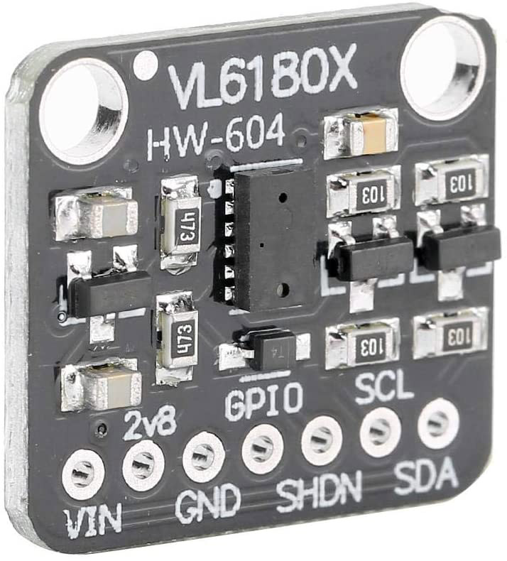
Hardware Explained

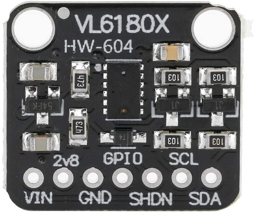
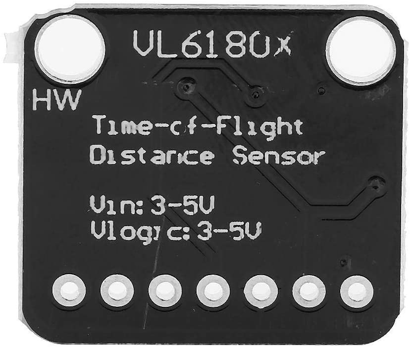
The VL6180X is a compact proximity sensor that utilizes time-of-flight technology to measure distances accurately. It operates using I2C communication, allowing for easy integration with Arduino and other microcontrollers. The sensor has a maximum range of 62 cm, but for this project, we will focus on the 20 cm range, which is suitable for most close-range applications.

The sensor operates on a voltage range of 2.6 to 3.5 volts and has low power consumption, making it ideal for battery-operated devices. It includes two GPIO pins that can be used for interrupt handling and power management, allowing for flexibility in more complex applications.

Datasheet Details

ManufacturerSTMicroelectronics
Part numberVL6180X
Logic/IO voltage2.6 - 3.5 V
Supply voltage2.6 - 3.5 V
Output current1.7 mA (typ.)
Peak current< 10 mA
PWM frequency guidanceN/A
Input logic thresholds0.3 x VCC (high), 0.2 x VCC (low)
Voltage drop / RDS(on) / saturationN/A
Thermal limits-20 to 70 °C
Package4.8 x 2.8 x 1 mm
Notes / variantsProximity and ambient light sensing

  • Ensure proper voltage supply between 2.6 to 3.5 V.
  • GPIO pins can be configured for various purposes, including interrupts.
  • Use I2C pull-up resistors if necessary.
  • Keep the sensor clean and unobstructed for accurate readings.
  • Check for proper wiring to avoid communication errors.
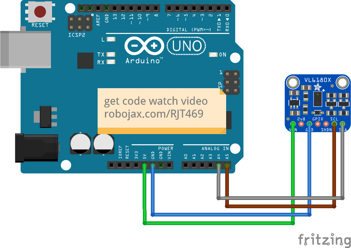
Wiring Instructions

Wiring VL6180 Obstacle Avoidance with Arduino
VL6180_dual_sensor_bb

To wire the VL6180X sensor to your Arduino, follow these steps:

  • Connect the VCC pin of the sensor to the 5V pin on the Arduino.
  • Connect the GND pin of the sensor to the GND pin on the Arduino.
  • Connect the SCL pin of the sensor to the A5 pin on the Arduino (I2C clock).
  • Connect the SDA pin of the sensor to the A4 pin on the Arduino (I2C data).

Make sure to double-check your connections to avoid any communication issues. If you plan to use multiple sensors, ensure that each sensor has a unique I2C address and adjust the wiring accordingly.

Code Examples & Walkthrough

Below is a brief excerpt from the setup code where we initialize the sensor and establish I2C communication:

void setup() {
  Serial.begin(115200);
  while (!Serial) { delay(1); }
  
  if (! vl.begin()) {
    Serial.println("Failed to find sensor");
    while (1);
  }
  Serial.println("Sensor found!");
}

In this section, we initialize the serial communication and check if the sensor is found. If the sensor is not detected, the program will halt, indicating an issue with the connection.

Next, let's look at the main loop where we read the distance and handle errors:

void loop() {
  uint8_t range = vl.readRange();
  uint8_t status = vl.readRangeStatus();

  if (status == VL6180X_ERROR_NONE) {
    Serial.print("Range: "); Serial.print(range);
    Serial.println("mm");
  }
  // Error handling omitted for brevity
  delay(50);
}

Here, we read the distance measurement into the variable range and check the status. If there are no errors, the distance is printed to the serial monitor. This is crucial for understanding how far the object is from the sensor.

The full code will load below this article for your reference.

Demonstration / What to Expect

When you run the code with the sensor wired correctly, you should see distance readings in millimeters printed on the serial monitor. If an object is placed within 20 cm of the sensor, the distance will be displayed accurately. If the object is too far or there are any issues, appropriate error messages will be shown. This process is demonstrated in the video (in video at 10:00).

Video Timestamps

  • 00:00 Start
  • 00:56 Introduction
  • 04:30 VL6080V Datasheet viewed
  • 06:58 Wiring shown
  • 07:32 Wiring for two or more sensors
  • 09:22 Installing library
  • 10:30 Arduino code explained (1 sensor)
  • 12:57 Code for 2 or more sensors
  • 19:35 Demonstration 1 sensor
  • 22:05 Demonstration with 2 sensors

图像

VL6080X sensor
VL6080X Sensor
VL6080X Sensor back of PCB
VL6080X Sensor top view
VL6080X Sensor verticle
Wiring VL6180 Obstacle Avoidance with Arduino
VL6180_wiring_new
VL6180_wiring_new
VL6180_dual_sensor_bb
361-Arduino code for VL6180X 20cm Time-of-Flight proximity sensor
语言: C++
/*
 *  Arduino code 
Using a single VL6180X 20cm Time-of-Flight proximity sensor with Arduino

View code for using a single VL6180X sensor: https://robojax.com?vid=robojax_VL6180X_laser2

 * Original code and library by https://github.com/adafruit/Adafruit_VL6180X
 * 
 * Written/updated by Ahmad Shamshiri for Robojax Robojax.com
 * on Mar 10, 2021  in Ajax, Ontario, Canada
Watch the video instruction for this sketch: https://youtu.be/_H9D0czQpSI


If you found this tutorial helpful, please support me so I can continue creating 
content like this. 
or make a donation using PayPal http://robojax.com/L/?id=64

* 
 * Code is available at http://robojax.com/learn/arduino

 * This code is "AS IS" without warranty or liability. Free to be used as long as you keep this note intact.
 * This code has been downloaded from Robojax.com
    This program is free software: you can redistribute it and/or modify
    it under the terms of the GNU General Public License as published by
    the Free Software Foundation, either version 3 of the License, or
    (at your option) any later version.

    This program is distributed in the hope that it will be useful,
    but WITHOUT ANY WARRANTY; without even the implied warranty of
    MERCHANTABILITY or FITNESS FOR A PARTICULAR PURPOSE.  See the
    GNU General Public License for more details.

    You should have received a copy of the GNU General Public License
    along with this program.  If not, see <https://www.gnu.org/licenses/>. 

*/
#include <Wire.h>
#include "Adafruit_VL6180X.h"

Adafruit_VL6180X vl = Adafruit_VL6180X();

void setup() {
  Serial.begin(115200);

  // wait for serial port to open on native usb devices
  while (!Serial) {
    delay(1);
  }
  
  Serial.println("Adafruit VL6180x test!");
  if (! vl.begin()) {
    Serial.println("Failed to find sensor");
    while (1);
  }
  Serial.println("Sensor found!");
}

void loop() {

  uint8_t range = vl.readRange();
  uint8_t status = vl.readRangeStatus();

  if (status == VL6180X_ERROR_NONE) {
    Serial.print("Range: "); Serial.print(range);
    Serial.println("mm");
  }
//  if(range <=76)
//  {
//    //do something
//  }

  // Some error occurred, print it out!
  
  if  ((status >= VL6180X_ERROR_SYSERR_1) && (status <= VL6180X_ERROR_SYSERR_5)) {
    Serial.println("System error");
  }
  else if (status == VL6180X_ERROR_ECEFAIL) {
    Serial.println("ECE failure");
  }
  else if (status == VL6180X_ERROR_NOCONVERGE) {
    Serial.println("No convergence");
  }
  else if (status == VL6180X_ERROR_RANGEIGNORE) {
    Serial.println("Ignoring range");
  }
  else if (status == VL6180X_ERROR_SNR) {
    Serial.println("Signal/Noise error");
  }
  else if (status == VL6180X_ERROR_RAWUFLOW) {
    Serial.println("Raw reading underflow");
  }
  else if (status == VL6180X_ERROR_RAWOFLOW) {
    Serial.println("Raw reading overflow");
  }
  else if (status == VL6180X_ERROR_RANGEUFLOW) {
    Serial.println("Range reading underflow");
  }
  else if (status == VL6180X_ERROR_RANGEOFLOW) {
    Serial.println("Range reading overflow");
  }
  delay(50);
}
450-Lesson 76: Using 2 ore more VL6180X 62cm Laser Distance Sensors with Arduino
语言: C++
/*
 *  Arduino code 
 * Lesson 76-2: Using two or more VL6180 Laser Distance Sensors with Arduino 
 * Adafruit code modified for this tutorial 
 * Using two or more VL6180X 20cm Time-of-Flight proximity sensors with Arduino
 *
 * View code for using single VL6180X sensors: https://robojax.com/course1/lecture76
 *
 * Original code and library by https://github.com/adafruit/Adafruit_VL6180X
 * 
 * Written/updated by Ahmad Shamshiri for Robojax Robojax.com
 * on Mar 12, 2021  in Ajax, Ontario, Canada
 * Watch the video instruction for this sketch: https://youtu.be/_H9D0czQpSI
 *
 *
 * Please watch video instruction for this code: https://youtu.be/_H9D0czQpSI
 *
 *  This video is part of Arduino Step by Step Course which starts here: https://youtu.be/-6qSrDUA5a8
 *
 *
 * If you found this tutorial helpful, please support me so I can continue creating 
 * content like this. 
 *
 * or make a donation using PayPal http://robojax.com/L/?id=64
 *  
 * This code is "AS IS" without warranty or liability. Free to be used as long as you keep this note intact.
 * This code has been downloaded from Robojax.com
 * This program is free software: you can redistribute it and/or modify
 * it under the terms of the GNU General Public License as published by
 * the Free Software Foundation, either version 3 of the License, or
 * (at your option) any later version.
 *
 * This program is distributed in the hope that it will be useful,
 * but WITHOUT ANY WARRANTY; without even the implied warranty of
 * MERCHANTABILITY or FITNESS FOR A PARTICULAR PURPOSE.  See the
 * GNU General Public License for more details.
 *
 * You should have received a copy of the GNU General Public License
 * along with this program.  If not, see <https://www.gnu.org/licenses/>. 
 *
 */

#include <Adafruit_VL6180X.h>

// address we will assign if dual sensor is present
#define LOX1_ADDRESS 0x30
#define LOX2_ADDRESS 0x31


// set the pins to shutdown
#define SHT_LOX1 7
#define SHT_LOX2 6


// Optional define GPIO pins to check to see if complete
#define GPIO_LOX1 4
#define GPIO_LOX2 3


#define TIMING_PIN 13

// objects for the VL6180X
Adafruit_VL6180X lox1 = Adafruit_VL6180X();
Adafruit_VL6180X lox2 = Adafruit_VL6180X();


// Setup mode for doing reads
typedef enum {RUN_MODE_DEFAULT, RUN_MODE_TIMED, RUN_MODE_ASYNC, RUN_MODE_GPIO, RUN_MODE_CONT} runmode_t;

runmode_t run_mode = RUN_MODE_DEFAULT;
uint8_t show_command_list = 1;

//==========================================================================
// Define some globals used in the continuous range mode
// Note: going to start table drive this part, may back up and do the rest later
Adafruit_VL6180X *sensors[] = {&lox1, &lox2};
const uint8_t COUNT_SENSORS = sizeof(sensors) / sizeof(sensors[0]);
const int sensor_gpios[COUNT_SENSORS] = {GPIO_LOX1, GPIO_LOX2}; // if any are < 0 will poll instead
uint8_t  tempRange;
uint8_t         sensor_ranges[COUNT_SENSORS];
uint8_t         sensor_status[COUNT_SENSORS];
// Could do with uint8_t for 8 sensors, but just in case...
const uint16_t  ALL_SENSORS_PENDING = ((1 << COUNT_SENSORS) - 1);
uint16_t        sensors_pending = ALL_SENSORS_PENDING;
uint32_t        sensor_last_cycle_time;


/*
    Reset all sensors by setting all of their XSHUT pins low for delay(10), then set all XSHUT high to bring out of reset
    Keep sensor #1 awake by keeping XSHUT pin high
    Put all other sensors into shutdown by pulling XSHUT pins low
    Initialize sensor #1 with lox.begin(new_i2c_address) Pick any number but 0x29 and it must be under 0x7F. Going with 0x30 to 0x3F is probably OK.
    Keep sensor #1 awake, and now bring sensor #2 out of reset by setting its XSHUT pin high.
    Initialize sensor #2 with lox.begin(new_i2c_address) Pick any number but 0x29 and whatever you set the first sensor to
*/
void setID() {
  // all reset
  digitalWrite(SHT_LOX1, LOW);
  digitalWrite(SHT_LOX2, LOW);

  delay(10);

  // all unreset
  digitalWrite(SHT_LOX1, HIGH);
  digitalWrite(SHT_LOX2, HIGH);

  delay(10);

  // activating LOX1 and reseting LOX2
  digitalWrite(SHT_LOX1, HIGH);
  digitalWrite(SHT_LOX2, LOW);


  // initing LOX1
  if (!lox1.begin()) {
    Serial.println(F("Failed to boot first VL6180X"));
    while (1);
  }
  lox1.setAddress(LOX1_ADDRESS);
  delay(10);

  // activating LOX2
  digitalWrite(SHT_LOX2, HIGH);
  delay(10);

  //initing LOX2
  if (!lox2.begin()) {
    Serial.println(F("Failed to boot second VL6180X"));
    while (1);
  }
  lox2.setAddress(LOX2_ADDRESS);
  delay(10);

 
}

void readSensor(Adafruit_VL6180X &vl) {

  float lux = vl.readLux(VL6180X_ALS_GAIN_5);

  uint8_t range = vl.readRange();

  uint8_t status = vl.readRangeStatus();

  if (status == VL6180X_ERROR_NONE) {
      tempRange = range;//save it for the moment
  }

  // Some error occurred, print it out!

  if  ((status >= VL6180X_ERROR_SYSERR_1) && (status <= VL6180X_ERROR_SYSERR_5)) {
    Serial.print("(System error)");
  }
  else if (status == VL6180X_ERROR_ECEFAIL) {
    Serial.print("(ECE failure)");
  }
  else if (status == VL6180X_ERROR_NOCONVERGE) {
    Serial.print("(No convergence)");
  }
  else if (status == VL6180X_ERROR_RANGEIGNORE) {
    Serial.print("(Ignoring range)");
  }
  else if (status == VL6180X_ERROR_SNR) {
    Serial.print("Signal/Noise error");
  }
  else if (status == VL6180X_ERROR_RAWUFLOW) {
    Serial.print("Raw reading underflow");
  }
  else if (status == VL6180X_ERROR_RAWOFLOW) {
    Serial.print("Raw reading overflow");
  }
  else if (status == VL6180X_ERROR_RANGEUFLOW) {
    Serial.print("Range reading underflow");
  }
  else if (status == VL6180X_ERROR_RANGEOFLOW) {
    Serial.print("Range reading overflow");
  }
}

void read_sensors() {
  readSensor(lox1);
  sensor_ranges[0]=tempRange;//save it now

  readSensor(lox2);
  sensor_ranges[1]=tempRange; //save it now 

  Serial.println();
}


//===============================================================
// Setup
//===============================================================
void setup() {
  Serial.begin(115200);

  // wait until serial port opens for native USB devices
  while (! Serial) {
    delay(1);
  }

  pinMode(SHT_LOX1, OUTPUT);
  pinMode(SHT_LOX2, OUTPUT);


  // Enable timing pin so easy to see when pass starts and ends
  pinMode(TIMING_PIN, OUTPUT);

#ifdef GPIO_LOX1
  // If we defined GPIO pins, enable them as PULL UP
  pinMode(GPIO_LOX1, INPUT_PULLUP);
  pinMode(GPIO_LOX2, INPUT_PULLUP);

#endif

  Serial.println("Shutdown pins inited...");

  digitalWrite(SHT_LOX1, LOW);
  digitalWrite(SHT_LOX2, LOW);

  digitalWrite(TIMING_PIN, LOW);
  Serial.println("All in reset mode...(pins are low)");


  Serial.println("Starting...");
  setID();

}

//===============================================================
// Loop
//===============================================================
void loop() {
 read_sensors();
      for(int i=0; i<COUNT_SENSORS; i++)
      {
        Serial.print("Sensor ");
        Serial.print(i);
        Serial.print(" :");        
        Serial.print(sensor_ranges[i]);
        Serial.print("mm");
        Serial.println();
      } 
//      if(sensor_ranges[1] >=76)
//      {
//        //do something here
//      }
  delay(100);
}

|||您可能需要的东西

文件📁

没有可用的文件。