このチュートリアルはの一部です: PCA9685で16または32個のサーボモーターを制御する
これらのビデオ付きチュートリアル集は、Arduino UNO、Nano、Mini、またはESP32を使用して32個以上のサーボモーターを制御するのに役立ちます。すべてのコードは提供されています。

Wi-Fiを介してESP32とPCA9685を使用し、デスクトップまたはモバイルフォンから32サーボを制御する V5
このチュートリアルでは、ESP32にWi-Fi経由で接続されたPCA9685 PWMコントローラーモジュールを使用して、32個のサーボモーターを制御する方法を学びます。この設定により、デスクトップまたはモバイルデバイスからアクセス可能なウェブインターフェースを通じて、各サーボを個別に、またはすべて一度に制御することができます。このガイドの終わりまでには、複数のサーボを簡単に管理できる完全に機能するシステムを手に入れることができます。

PCA9685モジュールは、PWM信号を使用して複数のサーボを制御する簡単な方法を提供し、ESP32はWi-Fi通信とウェブサーバー機能を処理します。各サーボモーターの角度は、各サーボ用のボタンを表示する使いやすいインターフェースを通じて調整できます。視覚的参照のために、動画(00:00の動画)をぜひチェックしてください。
ハードウェアの解説
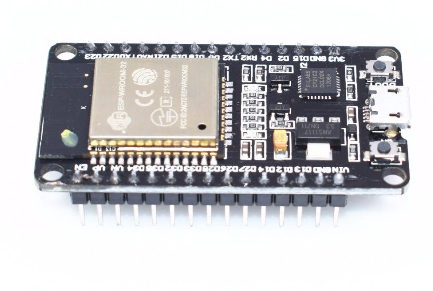
このプロジェクトは主にESP32マイクロコントローラとPCA9685 PWMコントローラを使用します。ESP32は、内蔵のWi-Fi機能を持つ強力なマイクロコントローラで、IoTプロジェクトに最適です。PCA9685は、最大64個のサーボを制御するためにカスケード接続できる16チャンネルのPWMコントローラです。これはI2Cプロトコルを介してESP32と通信し、複数のコントローラを接続して個別にアドレス指定できます。
各PCA9685モジュールのデフォルトI2Cアドレスは0x40です。複数のモジュールを使用する場合、特定のジャンパーをはんだ付けすることでアドレスを変更できます。例えば、最初のモジュールは0x40、2番目は0x41、といった具合です。このカスケード機能により、ESP32で追加のピンを必要とせずに多くのサーボを制御できます。
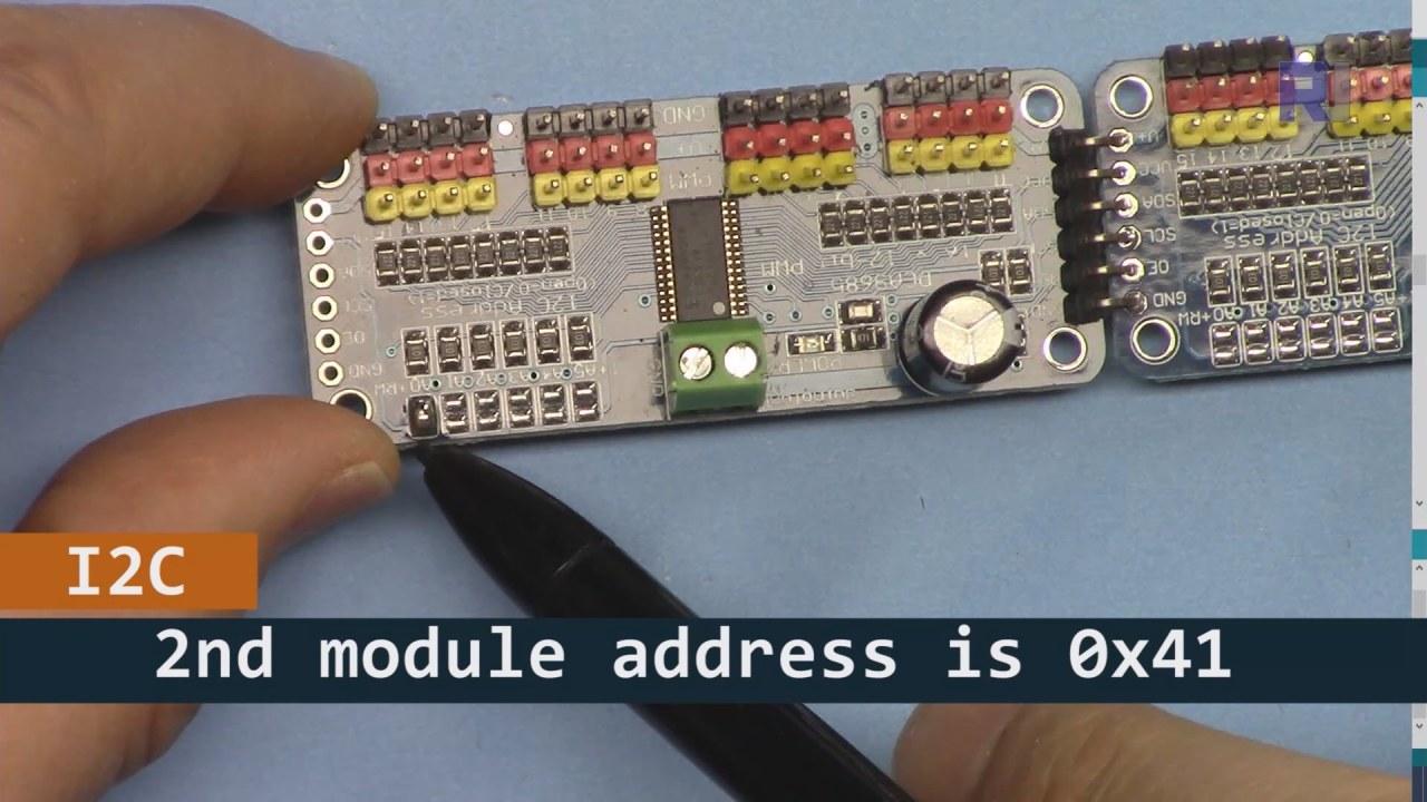
上の画像に示されているように、PCA9685ボード2(左側)では、I2Cアドレスを設定するためにそのパスをはんだ付けして、ボード1(右側)とは異なるようにしてください。
データシートの詳細
| メーカー | アダフルート |
|---|---|
| 部品番号 | PCA9685 |
| 論理/入出力電圧 | 2.3 V から 5.5 V |
| 供給電圧 | 2.3 Vから5.5 V |
| 出力電流(チャンネルごと) | 25 mA |
| ピーク電流(チャネルごと) | 100 mA |
| PWM周波数ガイダンス | 40 Hzから1000 Hzまで |
| 入力ロジックしきい値 | 0.3 Vcc (低) / 0.7 Vcc (高) |
| 電圧降下 / RDS(on)/飽和 | 0.5 V 最大 |
| 熱的制限 | 最大125 °C |
| パッケージ | TSSOP-28 |
| ノート / バリアント | カスケード接続の最大64サーボ |
- 適切な電源供給を確保してください(5V、2A推奨)。
- 必要に応じて、SDAおよびSCLラインにプルアップ抵抗を使用してください。
- 複数のPCA9685モジュールを使用する際は、I2Cアドレスを慎重に確認してください。
- 高出力アプリケーションのためにヒートシンクを考慮してください。
- 個々のサーボをテストして、正しく動作していることを確認してください。
一般的なI2Cピンのマッピング:SDA= GPIO 21、SCL= GPIO 22.
配線指示

PCA9685とESP32を配線するには、まず電源とグラウンドを接続します。正端子(V+PCA9685の)を電源の5V出力に接続します。PCA9685のグラウンド(GND)をESP32のグラウンドに接続します。両方のデバイスが共通のグラウンドを共有していることを確認してください。
次に、I2C通信のために、PCA9685のSDAピンをESP32のGPIO 21に接続し、SCLピンをGPIO 22に接続します。複数のPCA9685モジュールを使用している場合は、A0ジャンパーをはんだ付けして2番目のモジュールのアドレスを0x41に変更するなど、適切にアドレスを設定してください。その後、必要に応じてPCA9685のPWM出力ピンにサーボモーターを接続できます。
コード例とウォークスルー
コードは、必要なライブラリをインクルードし、2つのPCA9685ボードを初期化することから始まります。識別子は、maximumServoとservoAngleサーボの数と現在の角度をそれぞれ定義します。
Adafruit_PWMServoDriver board1 = Adafruit_PWMServoDriver(0x40);
Adafruit_PWMServoDriver board2 = Adafruit_PWMServoDriver(0x41);
int maximumServo = 32; // how many servos are connectedこの抜粋では、PCA9685オブジェクトの初期化がそれぞれのアドレスとともに示されています。変数maximumServo制御可能なサーボの総数を設定します。
中でsetup()関数、ボードが初期化され、Wi-Fi接続が確立されます。すべてのサーボの初期位置は、ループを使用して設定されます。
void setup() {
  board1.begin();
  board2.begin();
  board1.setPWMFreq(60);  // Analog servos run at ~60 Hz updates
  board2.setPWMFreq(60);
  //initial position of all servos
  for(int i=0; i < maximumServo; i++) {
    if(i < 16) {
      board1.setPWM(i, 0, angleToPulse(allServoPosition[i]));
    } else {
      board2.setPWM(i-15, 0, angleToPulse(allServoPosition[i]));
    }
  }
}このコードはPCA9685ボードを設定し、PWM周波数を設定します。すべてのサーボを定義された初期位置に初期化します。allServoPosition配列。
最後に、メインループはユーザーの入力に基づいてサーボを制御するために、受信したクライアントリクエストを処理します。
void loop() {
  server.handleClient();
  if (buttonPushed && (servoNumber >= 0 && servoNumber < maximumServo)) {
    if (servoNumber < 16) {
      board1.setPWM(servoNumber, 0, angleToPulse(allServoPosition[servoNumber]));
    } else {
      board2.setPWM(servoNumber-15, 0, angleToPulse(allServoPosition[servoNumber]));
    }
  }
  buttonPushed = 0;
}このループは、クライアントからのリクエストを継続的に処理し、押されたボタンに基づいてサーボ位置を更新します。変数buttonPushed各アクションの後にリセットされ、適切な制御が保証されます。
記事の下のセクションを参照してください。完全なコードが記載されています。
デモンストレーション / 期待すること
すべての設定が完了したら、ウェブインターフェースから各サーボを個別に、または一度にすべて制御できるようになるはずです。デバイス上の各サーボに対応するボタンをクリックすることで、サーボの角度を調整できます。システムは迅速に応答するはずですが、電力の制限がパフォーマンスに影響を与える可能性があることを念頭に置いてください(ビデオの14:30で)。
一般的な落とし穴には、I2Cアドレスが正しく割り当てられていることと、サーボモーターに十分な電力が供給されていることを確認することが含まれます。サーボモーターが反応しない場合は、配線と接続を再確認してください。
ビデオのタイムスタンプ
- 00:00 開始
- 01:19 はじめに
- 02:32 I2Cアドレスの設定
- 05:07 配線の説明
- 07:44 ESP32のためのArduino IDEを準備中
- 09:53 Arduinoのコードの説明
- 25:49 デスクトップでのデモンストレーション
- 31:52 モバイルフォンでのデモンストレーション
画像


このチュートリアルはの一部です: PCA9685で16または32個のサーボモーターを制御する
- PCA9685 16チャンネル 12ビット サーボコントローラ V1 用の Arduino コードとビデオ
- PCA9685モジュールとArduino V2スケッチを使用して16個のサーボモーターを制御する #1: 一つずつ
- PCA9685モジュールとArduino V2スケッチを使用した16個のサーボモーターの制御:個別サーボ制御
- Controlling 16 Servo Motors Using a PCA9685 Module and Arduino V2 Sketch #3: All Servos Together
- PCA9685モジュールとArduino V3スケッチを使用して32個のサーボモーターを制御する #1:すべてのサーボを一緒に
- PCA9685モジュールとESP32 V4を使用して32サーボモーターを制御する
/*
* Original PCA9685 Module library source: https://github.com/adafruit/Adafruit-PWM-Servo-Driver-Library
 *
 * This is the Arduino code PCA6985 32 channel servo controller
 * to control 32 Servo Motors over WiFi using ESP32 MCU
 *  get this code and wiring from for this video:  http://robojax.com/RJT365

 * Watch video for this code:  https://youtu.be/bvqfv-FrrLM
 *
 * Related Videos
V4 video of PCA9685 32 Servo with ESP32: https://youtu.be/JFdXB8Za5Os
V3 video of PCA9685 how to control 32 Servo motors https://youtu.be/6P21wG7N6t4
V2 Video of PCA9685 3 different ways to control Servo motors: https://youtu.be/bal2STaoQ1M
V1 Video introduction to PCA9685 to control 16 Servo  https://youtu.be/y8X9X10Tn1k
 *
 * Written by Ahmad Shamshiri for Robojax Video channel www.Robojax.com
 * Date: Feb 17, 2020, in Ajax, Ontario, Canada


or make donation using PayPal http://robojax.com/L/?id=64

 *  * This code is "AS IS" without warranty or liability. Free to be used as long as you keep this note intact.*
 * This code has been download from Robojax.com
    This program is free software: you can redistribute it and/or modify
    it under the terms of the GNU General Public License as published by
    the Free Software Foundation, either version 3 of the License, or
    (at your option) any later version.

    This program is distributed in the hope that it will be useful,
    but WITHOUT ANY WARRANTY; without even the implied warranty of
    MERCHANTABILITY or FITNESS FOR A PARTICULAR PURPOSE.  See the
    GNU General Public License for more details.

    You should have received a copy of the GNU General Public License
    along with this program.  If not, see <https://www.gnu.org/licenses/>.
 */
////////////////////// PCA9685 settings started
#include <Wire.h>

#include <Adafruit_PWMServoDriver.h>

// called this way, it uses the default address 0x40
Adafruit_PWMServoDriver board1 = Adafruit_PWMServoDriver(0x40);
Adafruit_PWMServoDriver board2 = Adafruit_PWMServoDriver(0x41);
int maximumServo = 32;//how many servos are connected

// Depending on your servo make, the pulse width min and max may vary, you
// want these to be as small/large as possible without hitting the hard stop
// for max range. You'll have to tweak them as necessary to match the servos you
// have!
// Watch video V1 to understand the two lines below: http://youtu.be/y8X9X10Tn1k
#define SERVOMIN  125 // this is the 'minimum' pulse length count (out of 4096)
#define SERVOMAX  575 // this is the 'maximum' pulse length count (out of 4096)

int servoAngle =0;
int servoStep = 10;

int stepDelay = 50;// 50 milliseconds
int servoAngleMin =0;
int servoAngleMax = 180;

// minimum angle of each servo
int allServoMin[]={
      0,    0,    0,    0,    0,    0,    0,    0,// 1 to 8
      0,    0,    0,    0,    0,    0,    0,    0,//9 to 16
      0,    0,    0,    0,    0,    0,    0,    0,//17 to 24
      0,    0,    0,    0,    0,    0,    0,    0};//25 to 32

//maximum value of each servo
int allServoMax[]={
      180,    180,    180,    180,    180,    180,    180,    180,// 1 to 8
      180,    180,    180,    180,    180,    180,    180,    180,//9 to 16
      180,    180,    180,    180,    180,    180,    180,    180,//17 to 24
      180,    180,    180,    180,    180,    180,    180,    180};//25 to 32

// initial position of servos
int allServoPosition[] ={
      0,    0,    0,    0,    0,    0,    0,    0,// 1 to 8
      0,    0,    0,    0,    0,    0,    0,    0,//9 to 16
      0,    0,    0,    0,    0,    0,    0,    0,//17 to 24
      0,    0,    0,    0,    0,    0,    0,    0};//25 to 32

int servoNumber = 100;//servo to move
int buttonPushed =0;
int allServo =0;

void handleServo();//this is prototype of function defined at the end of this code
int angleToPulse(int ang); //this is prototype of function defined at the end of this code
////////////////////////PCA9685 ended

#include "PCA9684_32Servo_ESP32.h"

#include <WiFi.h>
#include <WiFiClient.h>
#include <WebServer.h>
#include <ESPmDNS.h>

const char *ssid = "Robojax";
const char *password = "YouTube2020";

WebServer server(80);

const int led = 13;


/////////////////////////////////////
void handleRoot() {

String HTML_page = pageHeader_p1;

 if(allServo)
 {
 HTML_page.concat("<div class=\"btn\"><a class=\"angleButton colorAll\"  href=\"/servo?do=stop\">Stop Servo</a></div>");

 }else{
 HTML_page.concat("<div class=\"btn\"><a class=\"angleButton colorAll\"  href=\"/servo?do=all\">All Servo</a></div>");
 }

 for (int i=0; i < maximumServo; i++)
 {

  HTML_page.concat("<div class=\"btn\"><a class=\"angleButton colorBtn\"  href=\"/servo?move=");
  HTML_page.concat(i);
  HTML_page.concat("\">SRV ");
  HTML_page.concat(i+1);
  HTML_page.concat(" </a></div>");
 }

 HTML_page.concat("</body>\n</html>");
 server.send(200, "text/html", HTML_page);
}

void handleNotFound() {
  digitalWrite(led, 1);
  String message = "File Not Found\n\n";
  message += "URI: ";
  message += server.uri();
  message += "\nMethod: ";
  message += (server.method() == HTTP_GET) ? "GET" : "POST";
  message += "\nArguments: ";
  message += server.args();
  message += "\n";

  for (uint8_t i = 0; i < server.args(); i++) {
    message += " " + server.argName(i) + ": " + server.arg(i) + "\n";
  }

  server.send(404, "text/plain", message);
  digitalWrite(led, 0);
}


void setup() {
  board1.begin();
  board2.begin();
  board1.setPWMFreq(60);  // Analog servos run at ~60 Hz updates
  board2.setPWMFreq(60);
  //initial position of all servos
  for(int i=0; i < maximumServo; i++) {
    if(i < 16)
    {
      board1.setPWM(i, 0, angleToPulse(allServoPosition[i]) );
    }else{
      board2.setPWM(i-15, 0, angleToPulse(allServoPosition[i]) );
    }
  }//for end

    Serial.begin(115200);
    Serial.println("32 channel Servo test!");


  //Servo control using ESP32 from Robojax.com

  WiFi.mode(WIFI_STA);
  WiFi.begin(ssid, password);
  Serial.println("");


  // Wait for connection
  while (WiFi.status() != WL_CONNECTED) {
    delay(500);
    Serial.print(".");
  }

  Serial.println("");
  Serial.print("Connected to ");
  Serial.println(ssid);
  Serial.print("IP address: ");
  Serial.println(WiFi.localIP());


  if (MDNS.begin("robojaxESP32")) {
    Serial.print("MDNS responder started at http://");
    Serial.println("robojaxESP32");
  }

  server.on("/", handleRoot);
  server.on("/servo", HTTP_GET, handleServo);

  server.onNotFound(handleNotFound);
  server.begin();
  Serial.println("HTTP server started");
}

void loop() {
	server.handleClient();
  if(allServo ){

    for( int angle =servoAngleMin; angle <= servoAngleMax; angle +=servoStep){
      for(int i=0; i<16; i++)
        {

            board2.setPWM(i, 0, angleToPulse(angle) );
            board1.setPWM(i, 0, angleToPulse(angle) );
        }
        delay(stepDelay);
    }

// robojax PCA9865 32 channel Servo control
  delay(100);

  }//if pushed
  if(false){
  Serial.print("Servo #");
  Serial.print (servoNumber);
  Serial.print(" Angle ");
  Serial.println(allServoPosition[servoNumber]);
  }


  if( buttonPushed && (servoNumber >=0 && servoNumber < maximumServo) ){
    if(servoNumber < 16)
    {
      board1.setPWM(servoNumber, 0, angleToPulse(allServoPosition[servoNumber]) );
    }else{
      board2.setPWM(servoNumber-15, 0, angleToPulse(allServoPosition[servoNumber]) );
    }
  }

   buttonPushed =0;
}


/*
 * handleServo()
 * update the buttonPushed varialbe
 * returns nothing
 * Written by Ahmad Shamshiri on Dec 29, 2019
 * www.Robojax.com
 * http://youTube.com/robojaxTV
 */
void handleServo() {
  if(server.arg("do") == "all" )
  {
    allServo =1;

  }else{
    allServo =0;
  }
   int servoNumberRequested= server.arg("move").toInt();

  if(servoNumberRequested >=0 && servoNumberRequested < maximumServo)
  {

    buttonPushed = 1;
    if(allServoPosition[servoNumberRequested] == allServoMin[servoNumberRequested] ) {
     allServoPosition[servoNumberRequested] = allServoMax[servoNumberRequested];
    }else{
     allServoPosition[servoNumberRequested] = allServoMin[servoNumberRequested];
    }
    servoNumber =servoNumberRequested;
  }

  handleRoot();
}//handleServo() end


/*
 * angleToPulse(int ang)
 * gets angle in degree and returns the pulse width
 * also prints the value on seial monitor
 * written by Ahmad Shamshiri for Robojax, Robojax.com
 */
int angleToPulse(int ang){
   int pulse = map(ang,0, 180, SERVOMIN,SERVOMAX);// map angle of 0 to 180 to Servo min and Servo max
   //Serial.print("Angle: ");Serial.print(ang);
   //Serial.print(" pulse: ");Serial.println(pulse);
   return pulse;
}
必要かもしれないもの
-
アマゾンAmazonでPCA9685を購入するamzn.to
-
アマゾンアマゾンのサーボモーターamzn.to
-
イーベイeBayでPCA9685を購入するebay.us
-
アリエクスプレスAliExpressからPCA9685を購入するs.click.aliexpress.com
-
アリエクスプレスAliExpressからSG90サーボモーター180または360を購入してください。s.click.aliexpress.com
-
バングッドBangoodでPCA9685を購入するbanggood.com
リソースと参考文献
-
外部PAC9685ライブラリ(GitHubから)github.com
ファイル📁
ファイルは利用できません。