Este tutorial es parte de: Control de 16 o 32 servomotores con PCA9685
Esta colección de tutoriales con video te ayuda a controlar 32 o más servomotores con Arduino UNO, Nano, Mini o ESP32. Se proporcionan todos los códigos.

Controla 32 servos por Wi-Fi utilizando ESP32 y PCA9685 a través de escritorio o teléfono móvil V5
En este tutorial, aprenderemos cómo controlar 32 servomotores utilizando el módulo controlador PWM PCA9685 conectado al ESP32 a través de Wi-Fi. Esta configuración te permite controlar cada servomotor individualmente o todos a la vez a través de una interfaz web accesible desde un dispositivo de escritorio o móvil. Al final de esta guía, tendrás un sistema completamente funcional capaz de gestionar múltiples servos con facilidad.

El módulo PCA9685 proporciona una manera sencilla de controlar múltiples servos utilizando señales PWM, mientras que el ESP32 maneja la comunicación Wi-Fi y la funcionalidad del servidor web. Podrás ajustar el ángulo de cada motor servo a través de una interfaz fácil de usar que muestra botones para cada servo. Para una referencia visual, asegúrate de revisar el video (en el video a las 00:00).
Hardware Explicado
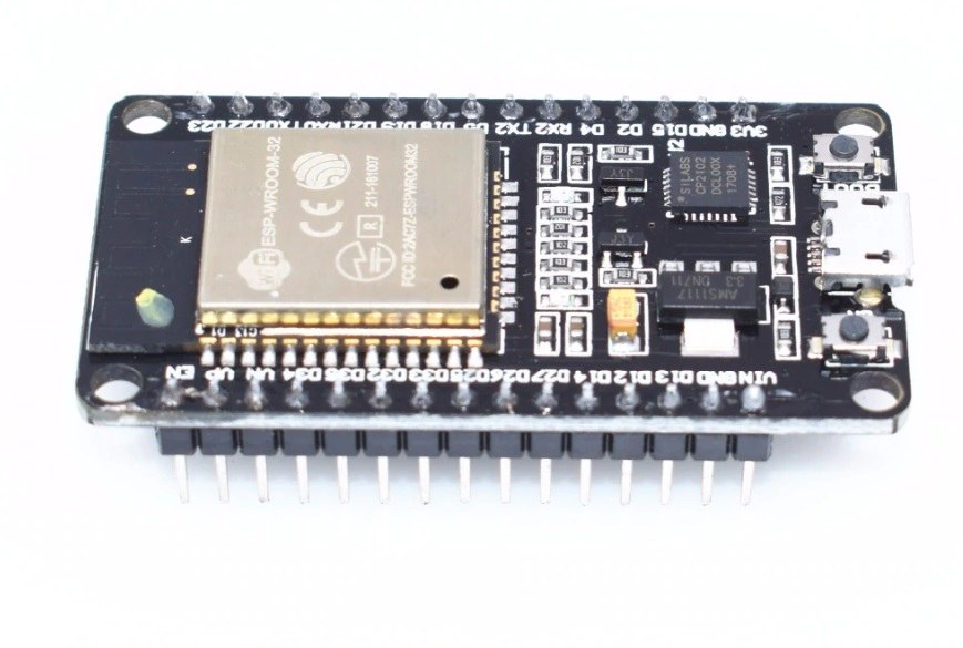
Este proyecto utiliza principalmente el microcontrolador ESP32 y el controlador PWM PCA9685. El ESP32 es un microcontrolador potente con capacidades de Wi-Fi integradas, lo que lo hace ideal para proyectos de IoT. El PCA9685 es un controlador PWM de 16 canales que se puede encadenar para controlar hasta 64 servomotores. Se comunica con el ESP32 a través del protocolo I2C, lo que permite conectar múltiples controladores y dirigirse a ellos de forma individual.
Cada módulo PCA9685 tiene una dirección I2C predeterminada de 0x40. Al utilizar múltiples módulos, puedes cambiar sus direcciones soldando conectores específicos. Por ejemplo, el primer módulo puede estar en 0x40, el segundo en 0x41, y así sucesivamente. Esta capacidad de conexión en cascada permite el control de muchos servos sin necesidad de pines adicionales en el ESP32.
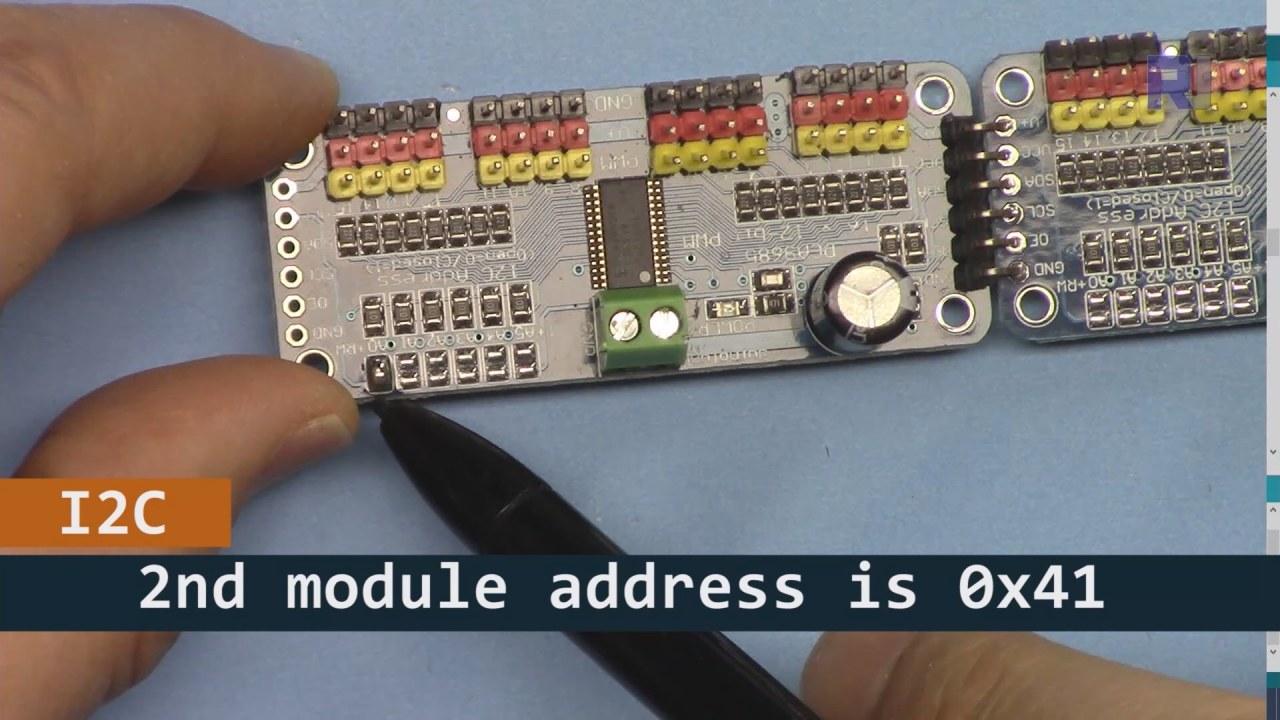
Como se muestra en la imagen de arriba, para la placa PCA9685 2 (a la izquierda), asegúrate de soldar ese camino para establecer la dirección I2C de manera que sea diferente de la placa 1 (a la derecha).
Detalles de la hoja de datos
| Fabricante | Adafruit |
|---|---|
| Número de parte | PCA9685 |
| Voltaje de lógica/IO | 2.3 V a 5.5 V |
| Voltaje de suministro | 2.3 V a 5.5 V |
| Corriente de salida (por canal) | 25 mA |
| Corriente máxima (por canal) | 100 mA |
| Orientación sobre la frecuencia PWM | 40 Hz a 1000 Hz |
| Umbrales lógicos de entrada | 0.3 Vcc (bajo) / 0.7 Vcc (alto) |
| Caída de voltaje / RDS(on)saturación | 0.5 V máx |
| Límites térmicos | 125 °C máx |
| Paquete | TSSOP-28 |
| Notas / variantes | Hasta 64 servomotores en cascada |
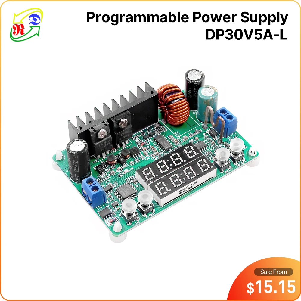
- Asegúrese de tener un suministro de energía adecuado (5V, 2A recomendado).
- Utilice resistencias pull-up en las líneas SDA y SCL si es necesario.
- Verifica cuidadosamente las direcciones I2C al utilizar múltiples módulos PCA9685.
- Considerar la disipación de calor para aplicaciones de alta potencia.
- Pruebe los servos individualmente para asegurar su correcto funcionamiento.
Mapeo de pines I2C comunes:SDA= GPIO 21,SCL= GPIO 22.
Instrucciones de cableado

Para cablear el PCA9685 y el ESP32, comienza conectando la alimentación y el terreno. Conecta el terminal positivo (V+) del PCA9685 a la salida de 5V de tu fuente de alimentación. Conecta el ground (GND) del PCA9685 al ground del ESP32. Asegúrate de que ambos dispositivos compartan un común ground.
A continuación, para la comunicación I2C, conecta el pin SDA del PCA9685 al GPIO 21 del ESP32 y el pin SCL al GPIO 22. Si estás utilizando varios módulos PCA9685, asegúrate de que estén adecuadamente direccionados soldando el puente A0 para cambiar la dirección del segundo módulo a 0x41, y así sucesivamente. Después de eso, puedes conectar los servomotores a los pines de salida PWM del PCA9685 según sea necesario.
Ejemplos de código y guía paso a paso
El código comienza incluyendo las bibliotecas necesarias e inicializando dos placas PCA9685. Los identificadores comomaximumServoyservoAngledefine el número de servos y el ángulo actual, respectivamente.
Adafruit_PWMServoDriver board1 = Adafruit_PWMServoDriver(0x40);
Adafruit_PWMServoDriver board2 = Adafruit_PWMServoDriver(0x41);
int maximumServo = 32; // how many servos are connected
Este extracto muestra la inicialización de los objetos PCA9685 con sus respectivas direcciones. La variablemaximumServoestablece el número total de servos que se pueden controlar.
En elsetup()función, se inicializan las placas y se establece la conexión Wi-Fi. La posición inicial de todos los servos se configura utilizando un bucle.
void setup() {
  board1.begin();
  board2.begin();
  board1.setPWMFreq(60);  // Analog servos run at ~60 Hz updates
  board2.setPWMFreq(60);
  //initial position of all servos
  for(int i=0; i < maximumServo; i++) {
    if(i < 16) {
      board1.setPWM(i, 0, angleToPulse(allServoPosition[i]));
    } else {
      board2.setPWM(i-15, 0, angleToPulse(allServoPosition[i]));
    }
  }
}
Este código configura las placas PCA9685 y establece la frecuencia PWM. Inicializa todos los servos en sus posiciones de inicio, que están definidas en elallServoPositionarray.
Finalmente, el bucle principal gestiona las solicitudes de los clientes entrantes para controlar los servos según la entrada del usuario.
void loop() {
  server.handleClient();
  if (buttonPushed && (servoNumber >= 0 && servoNumber < maximumServo)) {
    if (servoNumber < 16) {
      board1.setPWM(servoNumber, 0, angleToPulse(allServoPosition[servoNumber]));
    } else {
      board2.setPWM(servoNumber-15, 0, angleToPulse(allServoPosition[servoNumber]));
    }
  }
  buttonPushed = 0;
}
Este bucle procesa continuamente las solicitudes de los clientes y actualiza las posiciones del servo según el botón presionado. La variablebuttonPushedse restablece después de cada acción para garantizar un control adecuado.
Para el código completo, consulte la sección debajo del artículo.
Demostración / Qué Esperar
Una vez que todo esté configurado, deberías poder controlar cada servo individualmente o todos a la vez desde una interfaz web. Puedes ajustar los ángulos de los servos haciendo clic en los botones correspondientes a cada servo en tu dispositivo. El sistema debería responder rápidamente, pero ten en cuenta que las limitaciones de energía pueden afectar el rendimiento (en el video a las 14:30).
Las trampas comunes incluyen asegurarse de que las direcciones I2C estén correctamente asignadas y que se proporcione suficiente energía a los servomotores. Si los servomotores no responden, revisa nuevamente tu cableado y conexiones.
Sellos de tiempo del video
- 00:00 Inicio
- 01:19 Introducción
- 02:32 Configurando la dirección I2C
- 05:07 Explicación del cableado
- 07:44 Preparando el IDE de Arduino para ESP32
- 09:53 Código de Arduino explicado
- 25:49 Demostración en el escritorio
- 31:52 Demostración en teléfono móvil
Imágenes


Este tutorial es parte de: Control de 16 o 32 servomotores con PCA9685
- Código y vídeo de Arduino para el controlador de servos PCA9685 de 16 canales y 12 bits V1
- Controla 16 servomotores utilizando un módulo PCA9685 y un sketch de Arduino V2 #1: Uno por uno.
- Controlando 16 Servomotores utilizando un módulo PCA9685 y el sketch de Arduino V2: Control individual de servos.
- Controlling 16 Servo Motors Using a PCA9685 Module and Arduino V2 Sketch #3: All Servos Together
- Controlando un motor servo de 32 utilizando un módulo PCA9685 y el sketch de Arduino V3 #1: Todos los servos juntos
- Controlando un motor servo de 32 utilizando un módulo PCA9685 y un ESP32 V4
/*
 * Fuente original de la biblioteca del módulo PCA9685: https://github.com/adafruit/Adafruit-PWM-Servo-Driver-Library
 *
 * Este es el código de Arduino para el controlador de servo PCA9685 de 32 canales para controlar 32 motores servo a través de WiFi utilizando el MCU ESP32. Obtén este código y el cableado de este video: http://robojax.com/RJT365
 *
 * Mira el video para este código: https://youtu.be/bvqfv-FrrLM
 *
 * Videos relacionados
 * Video V4 de PCA9685 32 servo con ESP32: https://youtu.be/JFdXB8Za5Os
 * Video V3 de PCA9685 sobre cómo controlar 32 motores servo: https://youtu.be/6P21wG7N6t4
 * Video V2 de PCA9685 3 formas diferentes de controlar motores servo: https://youtu.be/bal2STaoQ1M
 * Video V1 introducción al PCA9685 para controlar 16 servo: https://youtu.be/y8X9X10Tn1k
 *
 * Escrito por Ahmad Shamshiri para el canal de videos Robojax www.Robojax.com
 * Fecha: 17 de febrero de 2020, en Ajax, Ontario, Canadá
 *
 * o haz una donación utilizando PayPal http://robojax.com/L/?id=64
 *
 * Este código es "COMO ESTÁ" sin garantía ni responsabilidad. Libre de ser utilizado siempre que mantengas esta nota intacta.*
 * Este código ha sido descargado de Robojax.com
 * Este programa es software libre: puedes redistribuirlo y/o modificarlo bajo los términos de la Licencia Pública General de GNU según lo publicado por la Fundación de Software Libre, ya sea la versión 3 de la Licencia, o (a tu elección) cualquier versión posterior.
 *
 * Este programa se distribuye con la esperanza de que sea útil, pero SIN NINGUNA GARANTÍA; ni siquiera la garantía implícita de COMERCIALIZABILIDAD o ADECUACIÓN PARA UN PROPÓSITO PARTICULAR. Consulta la Licencia Pública General de GNU para más detalles.
 *
 * Deberías haber recibido una copia de la Licencia Pública General de GNU junto con este programa. Si no, consulta <https://www.gnu.org/licenses/>.
 * /
 * ////////////////////// Configuraciones de PCA9685 iniciadas
 */
#include <Wire.h>

#include <Adafruit_PWMServoDriver.h>

 // llamada así, utiliza la dirección predeterminada 0x40
Adafruit_PWMServoDriver board1 = Adafruit_PWMServoDriver(0x40);
Adafruit_PWMServoDriver board2 = Adafruit_PWMServoDriver(0x41);
int maximumServo = 32; // cuántos servos están conectados

 // Dependiendo de la marca de su servomotor, el ancho de pulso mínimo y máximo puede variar, usted
 // quiero que estos sean lo más pequeños/grandes posibles sin llegar al límite máximo
 // para el rango máximo. Tendrás que ajustarlos según sea necesario para que coincidan con los servos que
 // ¡ten!
 // Mira el video V1 para entender las dos líneas a continuación: http://youtu.be/y8X9X10Tn1k
#define SERVOMIN  125 // este es el conteo de longitud de pulso 'mínima' (de 4096)
#define SERVOMAX  575 // este es el conteo de longitud de pulso 'máxima' (de un total de 4096)

int servoAngle =0;
int servoStep = 10;

int stepDelay = 50; // 50 milisegundos
int servoAngleMin =0;
int servoAngleMax = 180;

 // ángulo mínimo de cada servomotor
int allServoMin[]={
      0,    0,    0,    0,    0,    0,    0,    0, // 1 a 8
      0,    0,    0,    0,    0,    0,    0,    0, // 9 a 16
      0,    0,    0,    0,    0,    0,    0,    0, // 17 a 24
      0,    0,    0,    0,    0,    0,    0,    0}; // 25 a 32

 // valor máximo de cada servo
int allServoMax[]={
      180,    180,    180,    180,    180,    180,    180,    180, // 1 a 8
      180,    180,    180,    180,    180,    180,    180,    180, // 9 a 16
      180,    180,    180,    180,    180,    180,    180,    180, // 17 a 24
      180,    180,    180,    180,    180,    180,    180,    180}; // 25 a 32

 // posición inicial de los servos
int allServoPosition[] ={
      0,    0,    0,    0,    0,    0,    0,    0, // 1 a 8
      0,    0,    0,    0,    0,    0,    0,    0, // 9 a 16
      0,    0,    0,    0,    0,    0,    0,    0, // 17 a 24
      0,    0,    0,    0,    0,    0,    0,    0}; // 25 a 32

int servoNumber = 100; // servo para moverse
int buttonPushed =0;
int allServo =0;

void handleServo(); // este es un prototipo de la función definida al final de este código
int angleToPulse(int ang); // este es un prototipo de la función definida al final de este código
 // //////////////////////PCA9685 finalizado

#include "PCA9684_32Servo_ESP32.h"

#include <WiFi.h>
#include <WiFiClient.h>
#include <WebServer.h>
#include <ESPmDNS.h>

const char *ssid = "Robojax";
const char *password = "YouTube2020";

WebServer server(80);

const int led = 13;


 // ///////////////////////////////////
void handleRoot() {

String HTML_page = pageHeader_p1;

 if(allServo)
 {
 HTML_page.concat("<div class=\"btn\"><a class=\"angleButton colorAll\"  href=\"/servo?do=stop\">Stop Servo</a></div>");

 }else{
 HTML_page.concat("<div class=\"btn\"><a class=\"angleButton colorAll\"  href=\"/servo?do=all\">All Servo</a></div>");
 }

 for (int i=0; i < maximumServo; i++)
 {

  HTML_page.concat("<div class=\"btn\"><a class=\"angleButton colorBtn\"  href=\"/servo?move=");
  HTML_page.concat(i);
  HTML_page.concat("\">SRV ");
  HTML_page.concat(i+1);
  HTML_page.concat(" </a></div>");
 }

 HTML_page.concat("</body>\n</html>");
 server.send(200, "text/html", HTML_page);
}

void handleNotFound() {
  digitalWrite(led, 1);
  String message = "File Not Found\n\n";
  message += "URI: ";
  message += server.uri();
  message += "\nMethod: ";
  message += (server.method() == HTTP_GET) ? "GET" : "POST";
  message += "\nArguments: ";
  message += server.args();
  message += "\n";

  for (uint8_t i = 0; i < server.args(); i++) {
    message += " " + server.argName(i) + ": " + server.arg(i) + "\n";
  }

  server.send(404, "text/plain", message);
  digitalWrite(led, 0);
}


void setup() {
  board1.begin();
  board2.begin();
  board1.setPWMFreq(60); // Los servos analógicos funcionan con actualizaciones de ~60 Hz.
  board2.setPWMFreq(60);
 // posición inicial de todos los servos
  for(int i=0; i < maximumServo; i++) {
    if(i < 16)
    {
      board1.setPWM(i, 0, angleToPulse(allServoPosition[i]) );
    }else{
      board2.setPWM(i-15, 0, angleToPulse(allServoPosition[i]) );
    }
  } // para fin

    Serial.begin(115200);
    Serial.println("32 channel Servo test!");


 // Control de servos utilizando ESP32 de Robojax.com

  WiFi.mode(WIFI_STA);
  WiFi.begin(ssid, password);
  Serial.println("");


 // Esperar conexión
  while (WiFi.status() != WL_CONNECTED) {
    delay(500);
    Serial.print(".");
  }

  Serial.println("");
  Serial.print("Connected to ");
  Serial.println(ssid);
  Serial.print("IP address: ");
  Serial.println(WiFi.localIP());


  if (MDNS.begin("robojaxESP32")) {
    Serial.print("MDNS responder started at http: // ");
    Serial.println("robojaxESP32");
  }

  server.on("/", handleRoot);
  server.on("/servo", HTTP_GET, handleServo);

  server.onNotFound(handleNotFound);
  server.begin();
  Serial.println("HTTP server started");
}

void loop() {
	server.handleClient();
  if(allServo ){

    for( int angle =servoAngleMin; angle <= servoAngleMax; angle +=servoStep){
      for(int i=0; i<16; i++)
        {

            board2.setPWM(i, 0, angleToPulse(angle) );
            board1.setPWM(i, 0, angleToPulse(angle) );
        }
        delay(stepDelay);
    }

 // robojax PCA9865 control de servos de 32 canales
  delay(100);

  } // si se presiona
  if(false){
  Serial.print("Servo #");
  Serial.print (servoNumber);
  Serial.print(" Angle ");
  Serial.println(allServoPosition[servoNumber]);
  }


  if( buttonPushed && (servoNumber >=0 && servoNumber < maximumServo) ){
    if(servoNumber < 16)
    {
      board1.setPWM(servoNumber, 0, angleToPulse(allServoPosition[servoNumber]) );
    }else{
      board2.setPWM(servoNumber-15, 0, angleToPulse(allServoPosition[servoNumber]) );
    }
  }

   buttonPushed =0;
}


/*
 * handleServo()
 * actualizar la variable buttonPushed
 * no devuelve nada
 * Escrito por Ahmad Shamshiri el 29 de diciembre de 2019
 * www.Robojax.com
 * http://youTube.com/robojaxTV
 */
void handleServo() {
  if(server.arg("do") == "all" )
  {
    allServo =1;

  }else{
    allServo =0;
  }
   int servoNumberRequested= server.arg("move").toInt();

  if(servoNumberRequested >=0 && servoNumberRequested < maximumServo)
  {

    buttonPushed = 1;
    if(allServoPosition[servoNumberRequested] == allServoMin[servoNumberRequested] ) {
     allServoPosition[servoNumberRequested] = allServoMax[servoNumberRequested];
    }else{
     allServoPosition[servoNumberRequested] = allServoMin[servoNumberRequested];
    }
    servoNumber =servoNumberRequested;
  }

  handleRoot();
} // handleServo() fin


/*
 * angleToPulse(int ang)
 * obtiene el ángulo en grados y devuelve el ancho del pulso
 * también imprime el valor en el monitor serie
 * escrito por Ahmad Shamshiri para Robojax, Robojax.com
 */
int angleToPulse(int ang){
   int pulse = map(ang,0, 180, SERVOMIN,SERVOMAX); // mapear el ángulo de 0 a 180 a Servo min y Servo max
 // Serial.print("Ángulo: ");Serial.print(ang);
 // Serial.print(" pulso: ");Serial.println(pulso);
   return pulse;
}
Cosas que podrías necesitar
-
AmazonasCompra PCA9685 en Amazonamzn.to
-
AmazonasMotor servo en Amazonamzn.to
-
eBayCompra PCA9685 en eBayebay.us
-
AliExpressCompra el servo motor SG90 de 180 o 360 en AliExpress.s.click.aliexpress.com
-
AliExpressCompra PCA9685 en AliExpresss.click.aliexpress.com
-
BanggoodComprar PCA9685 en Banggoodbanggood.com
Recursos y referencias
-
ExternoBiblioteca PAC9685 (de GitHub)github.com
Archivos📁
No hay archivos disponibles.