How to Use a YYNMOS-4 4-Channel MOSFET to Control 5A to 20A DC Motors or LED Light Strips
In this tutorial, we will explore how to control various DC loads, such as motors and LED light strips, using the YYNMOS-4 4-channel MOSFET module. This module allows you to manage the intensity of lights or the speed of motors effectively. With its capability to handle loads between 5A to 20A, it can be an essential component in your electronic projects.

We will connect the MOSFET module to an Arduino, allowing us to control the loads through PWM (Pulse Width Modulation). This approach enables smooth control over the operation of motors and lights. For a visual guide, I recommend watching the associated video (in video at 00:00).
Hardware Explained
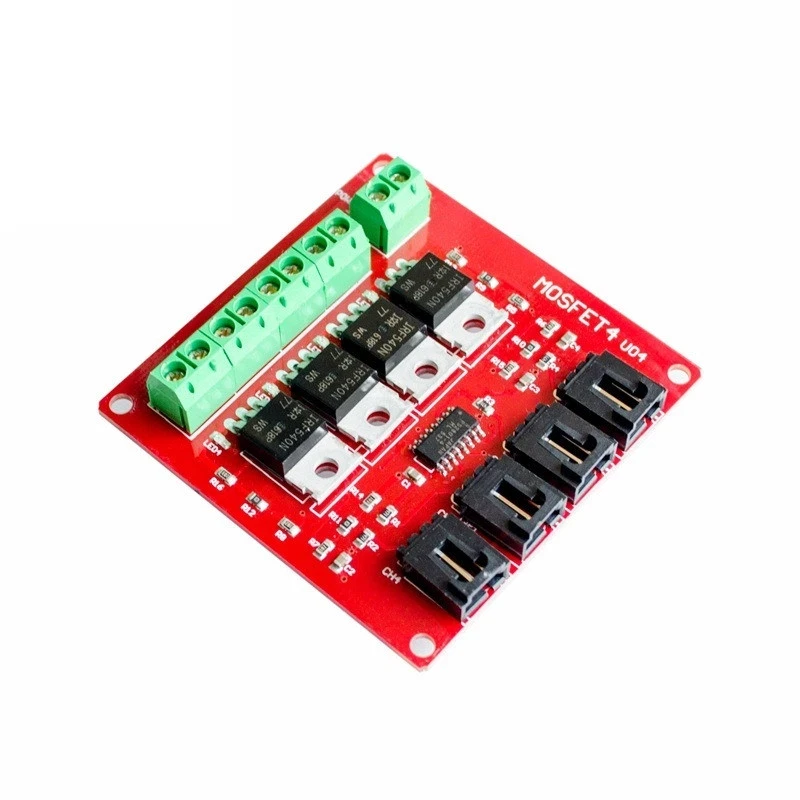
The YYNMOS-4 module includes four MOSFETs that can handle significant currents, making it ideal for driving various loads. Each MOSFET operates with low resistance (10 to 16 milli-ohms when on), allowing for efficient power delivery. You can connect up to four devices with a maximum current of 5A each, and with proper heatsinking, this can be increased to 20A.
In addition to the MOSFETs, the module features input terminals for control signals and output terminals for connecting your loads. The input can accept signals from 3V to 20V, making it compatible with most microcontrollers, including Arduino. The module also includes LEDs to indicate the status of each output, providing visual feedback during operation.
Datasheet Details
| Manufacturer | YYNMOS |
|---|---|
| Part number | YYNMOS-4 |
| Logic/IO voltage | 3–20 V |
| Supply voltage | 5–36 V |
| Output current (per channel) | 5 A |
| Peak current (per channel) | 20 A |
| PWM frequency guidance | ~1 kHz |
| Input logic thresholds | High: > 3 V, Low: < 1 V |
| Voltage drop / RDS(on) / saturation | 10–16 mΩ |
| Thermal limits | Up to 85°C |
| Package | Standard PCB module |
| Notes / variants | Compatible with PLCs |
- Ensure proper heatsinking for currents above 5A.
- Check voltage ratings before connecting loads.
- Use PWM signals for speed or intensity control.
- Be aware of thermal limits to prevent overheating.
- Double-check wiring to prevent short circuits.
Wiring Instructions


To wire the YYNMOS-4 module, begin by connecting the power supply. Connect the positive terminal of your power source to the DC+ terminal on the module and the negative terminal to the DC- terminal. Each load you wish to control will connect to one of the output pairs. For instance, connect the positive of your load to the respective output terminal and the negative to the ground.
For control signals, connect the PWM-enabled pins from your Arduino to the corresponding input pins on the YYNMOS-4 module. For instance, if you are using pins 3, 5, 6, and 9 on the Arduino, connect them to the PWM inputs on the module. Ensure that the ground of the Arduino is also connected to the ground of the YYNMOS-4 module to maintain a common reference point.
Code Examples & Walkthrough
The following code snippet demonstrates how to define the necessary pins and control the motors or LEDs using PWM signals. The variable motor is an array holding the pin numbers for easy reference.
int pin1 = 3; // PWM pin for motor 1
int pin2 = 5; // PWM pin for motor 2
int pin3 = 6; // PWM pin for motor 3
int pin4 = 9; // PWM pin for motor 4
int motor[]={NULL,pin1, pin2, pin3, pin4};
In this excerpt, we define four PWM pins for controlling each motor or LED. The array motor allows us to easily reference these pins later in the code.
The loop() function shows how to activate the motors at different speeds:
void loop() {
   motorON(1, 75); // Run motor 1 at 75% speed
   delay(4000); // Wait for 4 seconds
   stop(1); // Stop motor 1
   delay(3000); // Wait for 3 seconds
}
This segment of the code activates motor 1 at 75% speed for 4 seconds, then stops it for 3 seconds. Adjusting the speed and timing allows for flexible control of the loads.
For the complete code, please refer to the full program loaded below the article.
Demonstration / What to Expect
Upon completing the wiring and uploading the code to your Arduino, you should observe the motors or LEDs responding to the PWM signals. The motors will start at the defined speeds and can be stopped or adjusted dynamically. If you notice any issues, check for reversed polarity or incorrect wiring, as these are common pitfalls (in video at 12:30).
Video Timestamps
- 00:00 Start
- 00:58 Hardware Explained
- 07:53 Wiring Explained
- 10:13 Arduino Code for YYNMOS-4 Explained
- 14:51 Demonstration without Arduino
- 16:32 Demonstration with Arduino
Images


++
/*
 * This is Arduino code to control 4 DC motors' speed or 4 LED light strips or other DC loads
 * by utilizing a YYNMOS-4 4-channel MOSFET module.

We can control 4 DC motors with voltage from 5V to 35V and 5A each.
Get the code and wiring from https://robojax.com/RJT338

 * Written by Ahmad Shamshiri on July 13, 2020
 * in Ajax, Ontario, Canada. www.robojax.com
 *
 *
 * Watch video instructions for this code: https://youtu.be/G9uHVcITHf8
 *

If you found this tutorial helpful, please support me so I can continue creating
content like this.

or make a donation using PayPal http://robojax.com/L/?id=64

 * This code has been downloaded from Robojax.com
    This program is free software: you can redistribute it and/or modify
    it under the terms of the GNU General Public License as published by
    the Free Software Foundation, either version 3 of the License, or
    (at your option) any later version.

    This program is distributed in the hope that it will be useful,
    but WITHOUT ANY WARRANTY; without even the implied warranty of
    MERCHANTABILITY or FITNESS FOR A PARTICULAR PURPOSE.  See the
    GNU General Public License for more details.

    You should have received a copy of the GNU General Public License
    along with this program.  If not, see <https://www.gnu.org/licenses/>.
 */

int pin1 = 3;//pwm
int pin2 = 5;//pwm
int pin3 = 6;//pwm
int pin4 = 9;//pwm
int ON = HIGH;
int OFF = LOW;
int motor[]={NULL,pin1, pin2, pin3, pin4};


void setup() {
  Serial.begin(9600);
  Serial.println("Robojax.com 4 DC Motor or LED");
  pinMode(motor[1], OUTPUT);
  pinMode(motor[2], OUTPUT);
  pinMode(motor[3], OUTPUT);
  pinMode(motor[4], OUTPUT);

}

void loop() {
   motorON(1, 75);//run motor 1 at 75% speed
   delay(4000);//for 4 seconds

   motorON(4, 100);//run motor 4 at 100% speed (or 100% light intensity)
   delay(4000); //for 4 seconds

   stop(1);//stop motor 1
   delay(3000);//keep it stopped for 3 seconds

   stop(4);//stop motor 4
   delay(3000);  //keep it stopped for 3 seconds
   for(int i=0; i<=100; i++)
   {
     motorON(1,i); //change speed of motor 1
     delay(100);
   }
  delay(3000);//keep running for 3 seconds
  stop(1);//stop motor 1
  delay(3000);//keep it stopped for 3 seconds

     for(int i=100; i>=0; i--)
   {
     motorON(1,i);  //change speed of motor 1
     delay(100);
   }
   delay(3000); //keep it running for 3 seconds


   for(int i=0; i<=100; i++)
   {
     motorON(4,i);
     delay(100);
   }
  delay(3000);//keep it at for 3 seconds

    for(int i=100; i>=0; i--)
   {
     motorON(4,i);
     delay(100);
   }

}// loop


/*
   motorON(int n, int sp)
 * @brief Runs the specific motor n with speed sp
 * @param n, is an integer from 1 to 4
 * @param sp, is speed in % from 0 to 100
 * @return does not return anything
 * Written by Ahmad Shamshiri
 * www.Robojax.com code July 13, 2020 in Ajax, Ontario, Canada
 */
void motorON(int n, int sp)
{
  if(n >=1 && n <=4)
  {
  int speed=map(sp, 0, 100, 0, 255);
  analogWrite(motor[n],speed);
  Serial.print("Load ");
  Serial.print(n);
  Serial.print(" @");
  Serial.print(sp);
  Serial.println("%");

  }else{
    Serial.println("Motor/load number should be between 1 and 4");
    while(1);// stop forever
  }

}//motorON(int n)


/*
   stop(int n)
 * @brief Stops the specific motor
 * @param n, is an integer from 1 to 4
 * @return does not return anything
 * Written by Ahmad Shamshiri
 * www.Robojax.com code July 13, 2020 in Ajax, Ontario, Canada
 */
void stop(int n)
{
  if(n >=1 && n <=4)
  {

  digitalWrite(motor[n], LOW);
  Serial.print("Load ");
  Serial.print(n);
  Serial.println(" Stopped");

  }else{
    Serial.println("Motor/load number should be between 1 and 4");
    while(1);// stop forever
  }

}//stop(int n)
Things you might need
-
Amazon
-
eBay
-
AliExpressPurchase YYNMOS-4 4 Channel MOSFET from AliExpresss.click.aliexpress.com
-
AliExpressPurchase YYNMOS-4 4 Channel MOSFET from AliExpresss.click.aliexpress.com
-
AliExpressPurchase YYNMOS-4 4 Channel MOSFET from AliExpresss.click.aliexpress.com
Resources & references
-
External1N4148 (T4) SMD fast-switching diode datasheet (PDF)pdf.datasheetcatalog.com
-
External60N03 MOSFET, 12mΩ, 30V, 45A datasheet (PDF)cdn.datasheetspdf.com
-
External
Files📁
No files available.