Review of XY-1250 10-50A, 60A, 3000W PWM Motor Speed Controller XY-1260
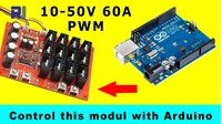
This guide provides a comprehensive review and hands-on testing of the XY-1250 (also known as XY-1260) PWM motor speed controller. This module is designed to control the speed of high-power DC motors by varying the pulse width modulation (PWM) signal. It is a robust and versatile solution for a wide range of applications where precise speed control of a large DC motor is required. We have separate tutorial showing how to use Arduino to control speed of this controller. View it here
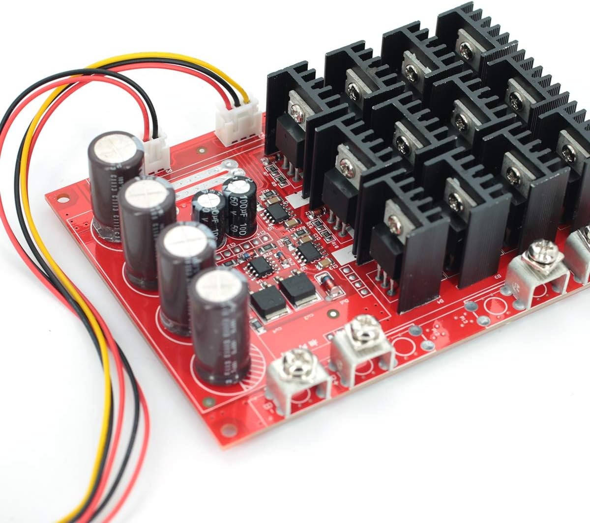
This controller is particularly useful for projects that demand high current handling. Some practical applications include:
- Controlling the speed of a large DC motor in an electric go-kart or scooter.
- Building a variable-speed drive for a treadmill motor in a DIY workshop tool, like a lathe or a bandsaw.
- Creating a high-power motor controller for an industrial conveyor belt or an automated gate system.
- Upgrading an existing motor control system that requires a simple, high-current PWM interface.
- Powering and controlling a heavy-duty winch with precise speed adjustments.
The review will cover the hardware components, a detailed demonstration of the module's performance with a small motor, and a rigorous stress test using an electronic load to determine its real-world current and power limits.
Hardware Overview
The XY-1250 is a substantial module built to handle significant power. The manufacturer rates it for a maximum input voltage of 50V and a maximum current of 60A. The total power is calculated by multiplying the input voltage by the current. Therefore, at the maximum 50V, it can theoretically supply 3000W (50V × 60A). If you use a lower voltage, such as 24V, the maximum power is correspondingly lower (24V × 60A = 1440W).
Let's break down the key components on the board:
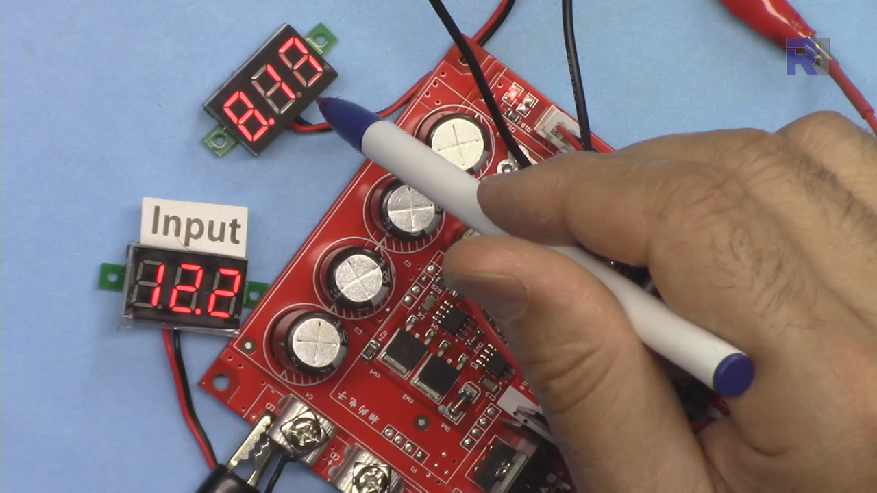
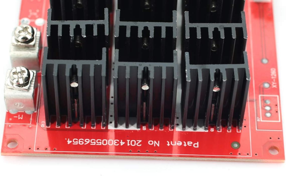
Input and Output Terminals: The module features heavy-duty screw terminals for the power input (battery) and the motor output (labeled M+ and M-). These are designed to accommodate fork or ring connectors for a secure and reliable connection.
Potentiometer and Switch: A potentiometer with an integrated on/off switch is included. This component allows you to control the motor's speed by adjusting the resistance and also serves as the main power switch for the controller.
Power Stage - MOSFETs: The heart of the controller is its output stage, which consists of eight NCE7190 power MOSFETs arranged in parallel. According to the datasheet mentioned in the video, each MOSFET can handle up to 90A. However, by using eight in parallel, the thermal load is distributed, allowing the module to handle high currents with a relatively small heatsink. The video notes that even if one MOSFET fails and is removed, the others can still share the load, though the maximum power capacity is reduced. The MOSFETs are biased separately with their own gate resistors for balanced current sharing.
Kickback Protection - Schottky Diodes: To protect the circuit from voltage spikes caused by the motor's inductive load, four 20100CT Schottky diode pairs are placed across the output. These diodes provide a path for the "kickback" current when the motor is switched off, preventing damage to the MOSFETs.
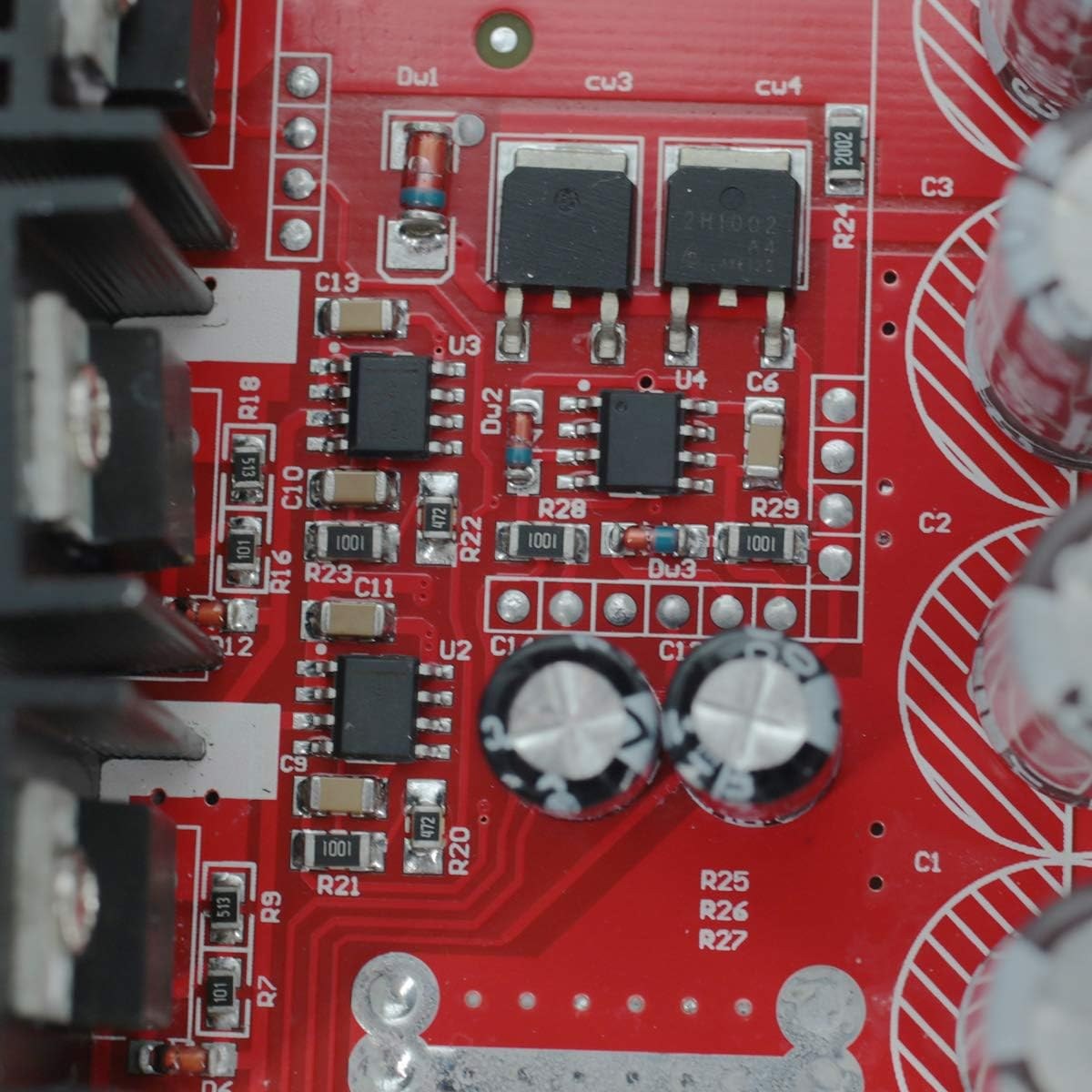
Control Circuitry: The PWM signal is generated by two 555 timer ICs. The potentiometer changes the resistance in the timing circuit, which in turn adjusts the duty cycle of the PWM signal and thus the motor's speed.
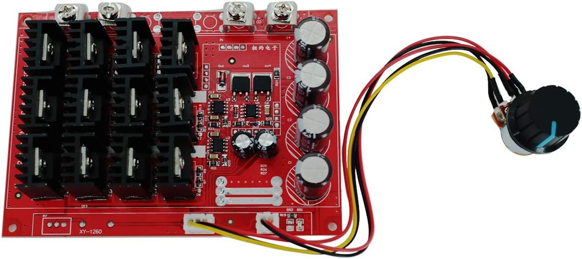
Physical Dimensions: The module measures approximately 122mm × 86.6mm and is 28mm deep. It weighs about 179.6 grams.
Wiring Guide
Wiring the XY-1250 is straightforward. The input terminals are clearly marked for the positive and negative wires from your power source (e.g., a battery). The output terminals are marked M+ and M- and connect directly to your DC motor.
Here is a simple wiring diagram for the module:
In this setup, the power source is connected to the input terminals on the left, and the motor is connected to the output terminals on the right. The included potentiometer plugs into the dedicated connector on the board, allowing you to turn the module on and off and control the motor's speed.
Demonstration with a DC Motor
The video begins the practical testing by connecting the module to a small DC motor. With a 12.1V input, the controller successfully varied the motor's speed from a minimum to a maximum. The test then moved to a larger, 130V DC motor (from a treadmill) running on a 12V supply. The controller was able to start and run this motor smoothly, and the speed increased as the input voltage was raised to 20V and then 30V, demonstrating the module's ability to handle larger loads.
Live Project: Stress Test with an Electronic Load
To truly test the controller's limits, the presenter connected it to an electronic load. This device can draw a precise, constant amount of power, allowing for a controlled stress test. The setup included a watt meter to monitor input voltage, current, and power, and the electronic load was set to constant power mode.
The test was conducted at 12V, starting with a 100W load, which drew about 9A. The controller remained cool. The load was then increased in steps. At 200W and 250W, the module was still very cool to the touch. At 300W, it drew about 28A, and the input power was measured at 326W, indicating about 26W of power dissipation. The test continued up to 350W, which was the limit of the electronic load. At this point, the current was 33A, and the module began to feel warm. The video notes a voltage drop at the output under high load, which is normal for this type of controller. During this test, one of the MOSFETs became excessively hot and failed. The presenter removed it, and the controller continued to function, proving the parallel design's resilience. The test continued, and the controller was able to handle 40A at 12V, with the MOSFETs remaining relatively cool while the Schottky diodes began to heat up.
Testing at 24V
A brief test was also conducted with a 24V supply. The controller was able to handle 20A without issue, demonstrating its capability at higher voltages as well.
Code Explanation
No code is required for this project. The XY-1250 is a standalone hardware module that operates using its own internal PWM generation circuitry, which is based on 555 timer ICs. There are no user-configurable software parameters or programming steps involved in its operation.
Conclusion and Recommendations
Based on the rigorous testing, the XY-1250 is a very solid and well-built module. At 12V, it can reliably handle up to 30A continuously without a cooling fan. The presenter recommends reducing the current limit to 20A or even 15A when operating at higher voltages (e.g., 24V or 36V) to prevent overheating. Adding an active cooling fan could potentially allow the module to handle even higher currents. The module's design, with its parallel MOSFETs and robust construction, makes it a highly recommended choice for high-power DC motor speed control applications.
Chapters
- [00:00] Introduction and Product Overview
- [01:27] Hardware Explained
- [06:03] Demonstration with DC Motor
- [09:17] Demonstration with Electronic Load
- [18:12] Demo: Electronic load with 24V
- [18:33] Conclusion Remarks
تصاویر
وسائل اور حوالہ جات
-
باہرونی
-
باہرونیDatasheet for NCE7190A MOSFET (8 pieces) (PDF)datasheet.lcsc.com
-
باہرونی
-
باہرونیSchottky diode MBR20100CTG datasheet (PDF)onsemi.com
-
باہرونیVL53L0X datasheet (PDF)st.com
فائلیں📁
کوئی فائلیں دستیاب نہیں ہیں۔