Ma trận LED 8x8 sử dụng mô-đun Arduino MAX7219
Trong hướng dẫn này, chúng ta sẽ học cách điều khiển một ma trận LED 8x8 bằng cách sử dụng mô-đun MAX7219 với Arduino. MAX7219 đơn giản hóa việc điều khiển nhiều LED, cho phép chúng ta hiển thị các ký tự và mẫu một cách dễ dàng. Cuối dự án này, bạn sẽ có thể hiển thị từ "ROBOJAX" trên ma trận.
Để đạt được điều này, chúng tôi sẽ sử dụng thư viện LedControl, được thiết kế đặc biệt để giao tiếp với MAX7219. Thư viện này cho phép chúng tôi gửi dữ liệu đến ma trận LED với nỗ lực tối thiểu. Nếu bạn muốn hiểu rõ hơn về cách đấu dây và mã, hãy chắc chắn kiểm tra video liên quan (trong video tại 0:30).
Giải thích phần cứng
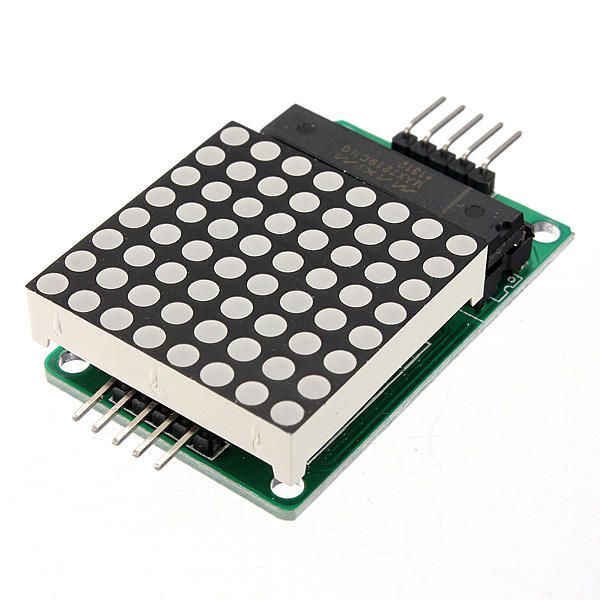
Các thành phần chính của dự án này bao gồm mô-đun MAX7219 và ma trận LED 8x8. MAX7219 là một mạch tích hợp quản lý hiển thị của các LED, xử lý các tín hiệu giao tiếp và điều khiển từ Arduino. Nó sử dụng giao diện nối tiếp, có nghĩa là chúng ta có thể điều khiển nhiều LED chỉ với một vài chân từ Arduino.
Ma trận LED 8x8 bao gồm 64 LED riêng lẻ được sắp xếp theo dạng lưới. Mỗi LED có thể được bật hoặc tắt bằng cách gửi các lệnh thích hợp qua MAX7219. Điều này cho phép hiển thị các ký tự và đồ họa khác nhau trên ma trận.
Chi tiết bảng dữ liệu
| Nhà sản xuất | Maxim Integrated |
|---|---|
| Số hiệu bộ phận | MAX7219 |
| Điện áp Logic/IO | 3.3V đến 5.5V |
| Điện áp cung cấp | 4.0V đến 5.5V |
| Dòng điện đầu ra (mỗi kênh) | 40 mA tối đa |
| Dòng điện đỉnh (mỗi kênh) | 100 mA tối đa |
| Hướng dẫn tần số PWM | 100 Hz |
| Ngưỡng logic đầu vào | 2.0V (cao) / 0.8V (thấp) |
| Sụt áp / RDS(on)/ bão hòa | 0.2V điển hình. |
| Giới hạn nhiệt độ | 150°C |
| Gói | 16-DIP |
| Ghi chú / biến thể | Cấu hình anot chung |
- Đảm bảo nguồn điện phù hợp (4.0V đến 5.5V).
- Sử dụng điện trở giới hạn dòng cho mỗi LED để ngăn ngừa hư hỏng.
- Giữ dây ngắn để tránh nhiễu.
- Giám sát sự tỏa nhiệt; sử dụng tản nhiệt nếu cần thiết.
- Kiểm tra lại các kết nối chân để tránh hiểu nhầm.
Hướng dẫn đấu dây
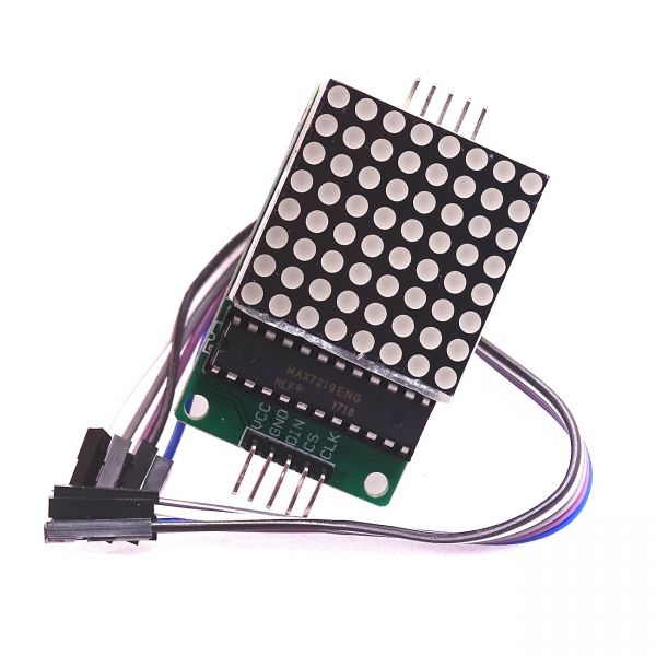
Để kết nối MAX7219 với Arduino, hãy kết nối các chân sau:
- Kết nối với
VCCchân của MAX7219 đến 5V của Arduino. - Kết nối với
GNDghim vào đất của Arduino. - Kết nối với
DINghim (Dữ liệu vào) vào chân Arduino 12. - Kết nối cái
CLKghim (Đồng hồ) vào chân Arduino 11. - Kết nối với
CSchân (Chọn Chip) đến chân 10 của Arduino.
Hãy chắc chắn kiểm tra rằng tất cả các kết nối đều an toàn trước khi bật nguồn cho mạch. Việc đấu dây rất đơn giản, nhưng nếu bạn gặp vấn đề, hãy xem xét kỹ lưỡng các kết nối (trong video tại 1:45).
Ví dụ mã và Hướng dẫn
Trong mã, chúng ta bắt đầu bằng cách bao gồm thư viện LedControl, điều này rất cần thiết để giao tiếp với MAX7219. Đoạn trích sau khởi tạo đối tượng LedControl:
LedControl lc=LedControl(12,11,10,1);Dòng này thiết lập chân dữ liệu, chân đồng hồ, chân chọn chip và số lượng thiết bị (1, trong trường hợp này). Tiếp theo, trongsetup()chức năng, chúng tôi đánh thức MAX7219 và thiết lập độ sáng hiển thị:
lc.shutdown(0,false);
lc.setIntensity(0,8);
lc.clearDisplay(0);
Điều này đảm bảo rằng màn hình đang hoạt động và sẵn sàng để hiển thị các ký tự. Chức năng chính điều khiển màn hình làwriteArduinoOnMatrix(), cái mà lần lượt làm sáng các hàng của ma trận để hiển thị các chữ cái.
Trình diễn / Những gì cần mong đợi
Khi mọi thứ đã được kết nối và mã đã được tải lên, ma trận LED sẽ hiển thị từ "ROBOJAX". Nếu màn hình không hoạt động, hãy kiểm tra các vấn đề như kết nối lỏng hoặc gán chân không chính xác. Ngoài ra, hãy đảm bảo nguồn điện là đủ (trong video tại 2:30).
Chương
- Giới thiệu (0:00)
- Tổng quan phần cứng (0:30)
- Hướng dẫn đấu dây (1:45)
- Hướng dẫn mã (2:15)
- Buổi biểu diễn (3:00)
Hình ảnh
/*
 * This video shows you how to use the MAX7219 module with an 8x8 LED matrix to display text or any characters on the LED.
 * Watch YouTube video: https://youtu.be/AAiDwBKs9uE
 *
 * Written by Ahmad Shamshiri for Robojax.com
 * on February 26, 2017 in Ajax, Ontario, Canada
 * Get this code and other Arduino codes from Robojax.com
 * Learn Arduino step by step in a structured course with all materials, wiring diagrams, and libraries
 * all in one place.

 ****************************
 * Get early access to my videos via Patreon and have your name mentioned at the end of every
 * video I publish on YouTube here: http://robojax.com/L/?id=63 (watch until the end of this video for a list of my Patrons)
 ****************************

 * Or make a donation using PayPal http://robojax.com/L/?id=64

 * This code is "AS IS" without warranty or liability. Free to be used as long as you keep this note intact.
 * This code has been downloaded from Robojax.com
    This program is free software: you can redistribute it and/or modify
    it under the terms of the GNU General Public License as published by
    the Free Software Foundation, either version 3 of the License, or
    (at your option) any later version.

    This program is distributed in the hope that it will be useful,
    but WITHOUT ANY WARRANTY; without even the implied warranty of
    MERCHANTABILITY or FITNESS FOR A PARTICULAR PURPOSE.  See the
    GNU General Public License for more details.

    You should have received a copy of the GNU General Public License
    along with this program.  If not, see <https://www.gnu.org/licenses/>.
*/


// We always have to include the library
// Based on a project posted https://github.com/wayoda/LedControl
#include "LedControl.h"

 /*
  Now we need a LedControl to work with.
  // Customized for RoboJax.com on February 26, 2017 in Ajax, Ontario, Canada.
  ***** These pin numbers will probably not work with your hardware *****
  pin 12 is connected to the DataIn
  pin 11 is connected to the CLK
  pin 10 is connected to CS
  We have only a single MAX72XX.
  */
 LedControl lc=LedControl(12,11,10,1);

 /* we always wait a bit between updates of the display */
 unsigned long delaytime=600;

 void setup() {
   /*
    The MAX72XX is in power-saving mode on startup,
    we have to do a wakeup call
    */
   lc.shutdown(0,false);
   /* Set the brightness to a medium value */
   lc.setIntensity(0,8);
   /* and clear the display */
   lc.clearDisplay(0);
 }

 /*
  This method will display the characters for the
  word "Arduino" one after the other on the matrix.
  (you need at least 5x7 LEDs to see the whole characters)
  */
 void writeArduinoOnMatrix() {
   /* here is the data for the characters */

   // K
   byte R[8]={B11111100,B10000100,B10000100,B11111000,B10100000,B10010000,B10001000,B10000100};
   byte O[8]={B00011000,B00100100,B01000010,B01000010,B01000010,B01000010,B00100100,B00011000};
   byte B[8]={B11111100,B10000100,B10000100,B11111000,B10001000,B10000100,B10000100,B11111100};
   byte J[8]={B00011110,B00000100,B00000100,B00000100,B10000100,B10000100,B01000100,B00111000};
   byte A[8]={B00111000,B01000100,B10000010,B11111110,B10000010,B10000010,B10000010,B10000010};
   byte X[8]={ B10000001,B01000010,B00100100,B00011000,B00011000,B00100100,B01000010,B10000001};
   byte love[8]={ B00000000,B01100110,B10011001,B10011001,B10000001,B01000010,B00100100,B00011000};


   /* Letter R */
   for (int i=0; i<8; i++){
   lc.setRow(0,i,R[i]);

   }

   delay(delaytime);
   for(int i=0; i<8; i++){
       lc.setRow(0,i,0);// this is for blank
   }
 //////////////// END of Letter R ///////

   /* Letter O */
   for (int i=0; i<8; i++){
   lc.setRow(0,i,O[i]);

   }

   delay(delaytime);
   for(int i=0; i<8; i++){
       lc.setRow(0,i,0);// this is for blank
   }
 //////////////// END of Letter O ///////


   /* Letter B */
   for (int i=0; i<8; i++){
   lc.setRow(0,i,B[i]);

   }

   delay(delaytime);
   for(int i=0; i<8; i++){
       lc.setRow(0,i,0);// this is for blank
   }
 //////////////// END of Letter B ///////

   /* Letter O */
   for (int i=0; i<8; i++){
   lc.setRow(0,i,O[i]);

   }

   delay(delaytime);
   for(int i=0; i<8; i++){
       lc.setRow(0,i,0);// this is for blank
   }
 //////////////// END of Letter O ///////

   /* Letter J */
   for (int i=0; i<8; i++){
   lc.setRow(0,i,J[i]);

   }

   delay(delaytime);
   for(int i=0; i<8; i++){
       lc.setRow(0,i,0);// this is for blank
   }
 //////////////// END of Letter J ///////

   /* Letter A */
   for (int i=0; i<8; i++){
   lc.setRow(0,i,A[i]);

   }

   delay(delaytime);
   for(int i=0; i<8; i++){
       lc.setRow(0,i,0);// this is for blank
   }
 //////////////// END of Letter A ///////

   /* Letter X */
   for (int i=0; i<8; i++){
   lc.setRow(0,i,X[i]);

   }

   delay(delaytime);
   for(int i=0; i<8; i++){
       lc.setRow(0,i,0);// this is for blank
   }
 //////////////// END of Letter X ///////


   /* love */
   for (int i=0; i<8; i++){
   lc.setRow(0,i,love[i]);

   }

   delay(delaytime);
   delay(delaytime);
   for(int i=0; i<8; i++){
       lc.setRow(0,i,0);// this is for blank
   }
 //////////////// END of Letter love ///////

 }// writeArduinoOnMatrix()  end


 void loop() {
   writeArduinoOnMatrix();

}/*
* This video shows you how to use the MAX7219 module with an 8x8 LED matrix to display text or any characters on the LED.
* Watch YouTube video: https://youtu.be/AAiDwBKs9uE
*
* Written by Ahmad S. for Robojax.com
* on February 26, 2017 in Ajax, Ontario, Canada
* Permission granted to share this code, given that this
* note is kept with the code.
* Disclaimer: This code is "AS IS" and for educational purposes only.
*/
// We always have to include the library
// Based on a project posted on https://github.com/wayoda/LedControl
#include "LedControl.h"
/*
Now we need a LedControl object to work with.
// Customized for RoboJax.com on February 26, 2017 in Ajax, Ontario, Canada.
***** These pin numbers will probably not work with your hardware *****
pin 1 is connected to the DataIn
pin 4 is connected to the CLK
pin 53 is connected to CS
We have only a single MAX72XX.
*/
LedControl lc=LedControl(1,4,53,1);// this line determines if this code can work with Arduino Mega or Arduino UNO
/* we always wait a bit between updates of the display */
unsigned long delaytime=600;
void setup() {
/*
The MAX72XX is in power-saving mode on startup,
we have to do a wakeup call
*/
lc.shutdown(0,false);
/* Set the brightness to a medium value */
lc.setIntensity(0,8);
/* and clear the display */
lc.clearDisplay(0);
}
/*
This method will display the characters for the
word "Arduino" one after the other on the matrix.
(you need at least 5x7 LEDs to see the whole characters)
*/
void writeArduinoOnMatrix() {
/* here is the data for the characters */
// K
byte R[8]={B11111100,B10000100,B10000100,B11111000,B10100000,B10010000,B10001000,B10000100};
byte O[8]={B00011000,B00100100,B01000010,B01000010,B01000010,B01000010,B00100100,B00011000};
byte B[8]={B11111100,B10000100,B10000100,B11111000,B10001000,B10000100,B10000100,B11111100};
byte J[8]={B00011110,B00000100,B00000100,B00000100,B10000100,B10000100,B01000100,B00111000};
byte A[8]={B00111000,B01000100,B10000010,B11111110,B10000010,B10000010,B10000010,B10000010};
byte X[8]={ B10000001,B01000010,B00100100,B00011000,B00011000,B00100100,B01000010,B10000001};
byte love[8]={ B00000000,B01100110,B10011001,B10011001,B10000001,B01000010,B00100100,B00011000};
/* Letter R */
for (int i=0; i<8; i++){
lc.setRow(0,i,R[i]);
}
delay(delaytime);
for(int i=0; i<8; i++){
lc.setRow(0,i,0);// this is for blank
}
/////////////// END of Letter R ///////
/* Letter O */
for (int i=0; i<8; i++){
lc.setRow(0,i,O[i]);
}
delay(delaytime);
for(int i=0; i<8; i++){
lc.setRow(0,i,0);// this is for blank
}
/////////////// END of Letter O ///////
/* Letter B */
for (int i=0; i<8; i++){
lc.setRow(0,i,B[i]);
}
delay(delaytime);
for(int i=0; i<8; i++){
lc.setRow(0,i,0);// this is for blank
}
/////////////// END of Letter B ///////
/* Letter O */
for (int i=0; i<8; i++){
lc.setRow(0,i,O[i]);
}
delay(delaytime);
for(int i=0; i<8; i++){
lc.setRow(0,i,0);// this is for blank
}
/////////////// END of Letter O ///////
/* Letter J */
for (int i=0; i<8; i++){
lc.setRow(0,i,J[i]);
}
delay(delaytime);
for(int i=0; i<8; i++){
lc.setRow(0,i,0);// this is for blank
}
/////////////// END of Letter J ///////
/* Letter A */
for (int i=0; i<8; i++){
lc.setRow(0,i,A[i]);
}
delay(delaytime);
for(int i=0; i<8; i++){
lc.setRow(0,i,0);// this is for blank
}
/////////////// END of Letter A ///////
/* Letter X */
for (int i=0; i<8; i++){
lc.setRow(0,i,X[i]);
}
delay(delaytime);
for(int i=0; i<8; i++){
lc.setRow(0,i,0);// this is for blank
}
/////////////// END of Letter X ///////
/* love */
for (int i=0; i<8; i++){
lc.setRow(0,i,love[i]);
}
delay(delaytime);
delay(delaytime);
for(int i=0; i<8; i++){
lc.setRow(0,i,0);// this is for blank
}
/////////////// END of love ///////
}// writeArduinoOnMatrix() end
void loop() {
writeArduinoOnMatrix();
}Nghĩ bạn có thể cần
-
AmazonMax7219 8x8 Matrix on Amazonamzn.to
-
eBayMax7219 8x8 Matrix on eBayebay.us
-
AliExpressMax7219 8x8 Matrix on AliExpresss.click.aliexpress.com
Tài nguyên & tài liệu tham khảo
-
Tài liệuView different board pin assignments for SPIarduino.cc
-
Bên ngoài
Tập tin📁
Các tập tin khác
-
Thư viện ma trận MAX7219 từ Robojax
robojax-MAX7219-matrix.zip0.01 MB -
8-Digit LED Display Library (from Robojax.com)
robojax_MAX7291_8_digits.zip