8x8 LED-matris med en MAX7219 Arduino-modul
I den här handledningen kommer vi att lära oss hur man styr en 8x8 LED-matris med en MAX7219-modul och en Arduino. MAX7219 förenklar styrningen av flera LED-lampor, vilket gör att vi enkelt kan visa tecken och mönster. I slutet av detta projekt kommer du att kunna visa ordet "ROBOJAX" på matrisen.
För att uppnå detta kommer vi att använda LedControl-biblioteket, som är speciellt utformat för att kommunicera med MAX7219. Detta bibliotek gör att vi kan skicka data till LED-matrisen med minimal ansträngning. Om du vill ha en tydligare förståelse av kopplingen och koden, se till att kolla på den tillhörande videon (i videon vid 0:30).
Hårdvara förklarad
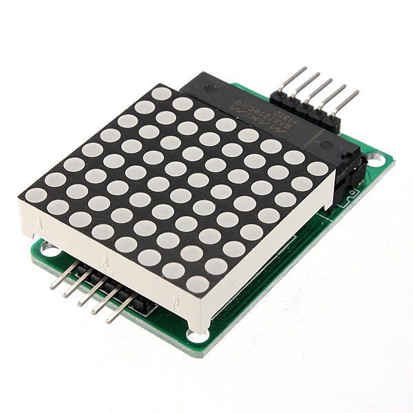
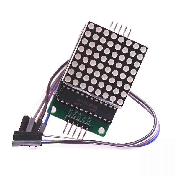
De primära komponenterna i detta projekt inkluderar MAX7219-modulen och 8x8 LED-matrisen. MAX7219 är en integrerad krets som hanterar visningen av LED-lamporna och sköter kommunikationen och kontrollsignalerna från Arduino. Den använder ett seriellt gränssnitt, vilket innebär att vi kan styra många LED-lampor med bara några få pinnar från Arduino.
8x8 LED-matrisen består av 64 individuella LED-lampor som är arrangerade i ett rutnät. Varje LED kan slås på eller av genom att skicka lämpliga kommandon via MAX7219. Detta möjliggör visning av olika tecken och grafik på matrisen.
Datablad Detaljer
| Tillverkare | Maxim Integrated |
|---|---|
| Delnummer | MAX7219 |
| Logik/IO-spänning | 3,3V till 5,5V |
| Försörjningsspänning | 4,0V till 5,5V |
| Utgångsström (per kanal) | 40 mA max |
| Spetsström (per kanal) | 100 mA max |
| PWM-frekvens vägledning | 100 Hz |
| Inmatningslogiktrösklar | 2,0V (hög) / 0,8V (låg) |
| Spänningsfall / RDS(on)/ mättnad | 0,2V typ. |
| Termiska gränser | 150°C |
| Paket | 16-DIP |
| Anteckningar / varianter | Vanlig anodkonfiguration |
- Säkerställ korrekt strömförsörjning (4,0V till 5,5V).
- Använd strömbegränsande motstånd för varje LED för att förhindra skador.
- Håll kablarna korta för att undvika störningar.
- Övervaka värmeavledning; använd en kylfläns om det behövs.
- Dubbelkolla pinanslutningar för att undvika misskommunikation.
Kopplingsanvisningar
För att koppla MAX7219 till Arduino, anslut följande stift:
- Anslut den
VCCpin av MAX7219 till Arduinos 5V. - Anslut den
GNDpin till Arduinos jord. - Anslut den
DINpin (Data In) till Arduino pin 12. - Anslut den
CLKkoppla (Klocka) till Arduino pin 11. - Anslut den
CSpin (Chip Select) till Arduino pin 10.
Se till att kontrollera att alla anslutningar är säkra innan du slår på kretsen. Ledningarna är raka, men om du stöter på problem, granska anslutningarna noggrant (i videon vid 1:45).
Kodexempel och genomgång
I koden börjar vi med att inkludera LedControl-biblioteket, som är avgörande för att kommunicera med MAX7219. Följande utdrag initierar LedControl-objektet:
LedControl lc=LedControl(12,11,10,1);Denna rad ställer in datapin, klockpin, chipvalspinne och antalet enheter (1, i det här fallet). Nästa, i densetup()funktion, vi väcker MAX7219 och ställer in visningsintensiteten:
lc.shutdown(0,false);
lc.setIntensity(0,8);
lc.clearDisplay(0);
Detta säkerställer att skärmen är aktiv och redo att visa tecken. Huvudfunktionen som driver skärmen ärwriteArduinoOnMatrix(), som sekventiellt tänder upp raderna i matrisen för att visa bokstäver.
Demonstration / Vad man kan förvänta sig
När allt är kopplat och koden är uppladdad, bör LED-matrisen visa ordet "ROBOJAX". Om displayen inte fungerar, kontrollera problem som lösa anslutningar eller felaktiga stiftkopplingar. Se också till att strömförsörjningen är tillräcklig (i videon vid 2:30).
Kapitel
- Introduktion (0:00)
- Översikt av hårdvara (0:30)
- Kopplingsanvisningar (1:45)
- Kodgenomgång (2:15)
- Demonstration (3:00)
Bilder
/*
 * This video shows you how to use the MAX7219 module with an 8x8 LED matrix to display text or any characters on the LED.
 * Watch YouTube video: https://youtu.be/AAiDwBKs9uE
 *
 * Written by Ahmad Shamshiri for Robojax.com
 * on February 26, 2017 in Ajax, Ontario, Canada
 * Get this code and other Arduino codes from Robojax.com
 * Learn Arduino step by step in a structured course with all materials, wiring diagrams, and libraries
 * all in one place.

 ****************************
 * Get early access to my videos via Patreon and have your name mentioned at the end of every
 * video I publish on YouTube here: http://robojax.com/L/?id=63 (watch until the end of this video for a list of my Patrons)
 ****************************

 * Or make a donation using PayPal http://robojax.com/L/?id=64

 * This code is "AS IS" without warranty or liability. Free to be used as long as you keep this note intact.
 * This code has been downloaded from Robojax.com
    This program is free software: you can redistribute it and/or modify
    it under the terms of the GNU General Public License as published by
    the Free Software Foundation, either version 3 of the License, or
    (at your option) any later version.

    This program is distributed in the hope that it will be useful,
    but WITHOUT ANY WARRANTY; without even the implied warranty of
    MERCHANTABILITY or FITNESS FOR A PARTICULAR PURPOSE.  See the
    GNU General Public License for more details.

    You should have received a copy of the GNU General Public License
    along with this program.  If not, see <https://www.gnu.org/licenses/>.
*/


// We always have to include the library
// Based on a project posted https://github.com/wayoda/LedControl
#include "LedControl.h"

 /*
  Now we need a LedControl to work with.
  // Customized for RoboJax.com on February 26, 2017 in Ajax, Ontario, Canada.
  ***** These pin numbers will probably not work with your hardware *****
  pin 12 is connected to the DataIn
  pin 11 is connected to the CLK
  pin 10 is connected to CS
  We have only a single MAX72XX.
  */
 LedControl lc=LedControl(12,11,10,1);

 /* we always wait a bit between updates of the display */
 unsigned long delaytime=600;

 void setup() {
   /*
    The MAX72XX is in power-saving mode on startup,
    we have to do a wakeup call
    */
   lc.shutdown(0,false);
   /* Set the brightness to a medium value */
   lc.setIntensity(0,8);
   /* and clear the display */
   lc.clearDisplay(0);
 }

 /*
  This method will display the characters for the
  word "Arduino" one after the other on the matrix.
  (you need at least 5x7 LEDs to see the whole characters)
  */
 void writeArduinoOnMatrix() {
   /* here is the data for the characters */

   // K
   byte R[8]={B11111100,B10000100,B10000100,B11111000,B10100000,B10010000,B10001000,B10000100};
   byte O[8]={B00011000,B00100100,B01000010,B01000010,B01000010,B01000010,B00100100,B00011000};
   byte B[8]={B11111100,B10000100,B10000100,B11111000,B10001000,B10000100,B10000100,B11111100};
   byte J[8]={B00011110,B00000100,B00000100,B00000100,B10000100,B10000100,B01000100,B00111000};
   byte A[8]={B00111000,B01000100,B10000010,B11111110,B10000010,B10000010,B10000010,B10000010};
   byte X[8]={ B10000001,B01000010,B00100100,B00011000,B00011000,B00100100,B01000010,B10000001};
   byte love[8]={ B00000000,B01100110,B10011001,B10011001,B10000001,B01000010,B00100100,B00011000};


   /* Letter R */
   for (int i=0; i<8; i++){
   lc.setRow(0,i,R[i]);

   }

   delay(delaytime);
   for(int i=0; i<8; i++){
       lc.setRow(0,i,0);// this is for blank
   }
 //////////////// END of Letter R ///////

   /* Letter O */
   for (int i=0; i<8; i++){
   lc.setRow(0,i,O[i]);

   }

   delay(delaytime);
   for(int i=0; i<8; i++){
       lc.setRow(0,i,0);// this is for blank
   }
 //////////////// END of Letter O ///////


   /* Letter B */
   for (int i=0; i<8; i++){
   lc.setRow(0,i,B[i]);

   }

   delay(delaytime);
   for(int i=0; i<8; i++){
       lc.setRow(0,i,0);// this is for blank
   }
 //////////////// END of Letter B ///////

   /* Letter O */
   for (int i=0; i<8; i++){
   lc.setRow(0,i,O[i]);

   }

   delay(delaytime);
   for(int i=0; i<8; i++){
       lc.setRow(0,i,0);// this is for blank
   }
 //////////////// END of Letter O ///////

   /* Letter J */
   for (int i=0; i<8; i++){
   lc.setRow(0,i,J[i]);

   }

   delay(delaytime);
   for(int i=0; i<8; i++){
       lc.setRow(0,i,0);// this is for blank
   }
 //////////////// END of Letter J ///////

   /* Letter A */
   for (int i=0; i<8; i++){
   lc.setRow(0,i,A[i]);

   }

   delay(delaytime);
   for(int i=0; i<8; i++){
       lc.setRow(0,i,0);// this is for blank
   }
 //////////////// END of Letter A ///////

   /* Letter X */
   for (int i=0; i<8; i++){
   lc.setRow(0,i,X[i]);

   }

   delay(delaytime);
   for(int i=0; i<8; i++){
       lc.setRow(0,i,0);// this is for blank
   }
 //////////////// END of Letter X ///////


   /* love */
   for (int i=0; i<8; i++){
   lc.setRow(0,i,love[i]);

   }

   delay(delaytime);
   delay(delaytime);
   for(int i=0; i<8; i++){
       lc.setRow(0,i,0);// this is for blank
   }
 //////////////// END of Letter love ///////

 }// writeArduinoOnMatrix()  end


 void loop() {
   writeArduinoOnMatrix();

}/*
* This video shows you how to use the MAX7219 module with an 8x8 LED matrix to display text or any characters on the LED.
* Watch YouTube video: https://youtu.be/AAiDwBKs9uE
*
* Written by Ahmad S. for Robojax.com
* on February 26, 2017 in Ajax, Ontario, Canada
* Permission granted to share this code, given that this
* note is kept with the code.
* Disclaimer: This code is "AS IS" and for educational purposes only.
*/
// We always have to include the library
// Based on a project posted on https://github.com/wayoda/LedControl
#include "LedControl.h"
/*
Now we need a LedControl object to work with.
// Customized for RoboJax.com on February 26, 2017 in Ajax, Ontario, Canada.
***** These pin numbers will probably not work with your hardware *****
pin 1 is connected to the DataIn
pin 4 is connected to the CLK
pin 53 is connected to CS
We have only a single MAX72XX.
*/
LedControl lc=LedControl(1,4,53,1);// this line determines if this code can work with Arduino Mega or Arduino UNO
/* we always wait a bit between updates of the display */
unsigned long delaytime=600;
void setup() {
/*
The MAX72XX is in power-saving mode on startup,
we have to do a wakeup call
*/
lc.shutdown(0,false);
/* Set the brightness to a medium value */
lc.setIntensity(0,8);
/* and clear the display */
lc.clearDisplay(0);
}
/*
This method will display the characters for the
word "Arduino" one after the other on the matrix.
(you need at least 5x7 LEDs to see the whole characters)
*/
void writeArduinoOnMatrix() {
/* here is the data for the characters */
// K
byte R[8]={B11111100,B10000100,B10000100,B11111000,B10100000,B10010000,B10001000,B10000100};
byte O[8]={B00011000,B00100100,B01000010,B01000010,B01000010,B01000010,B00100100,B00011000};
byte B[8]={B11111100,B10000100,B10000100,B11111000,B10001000,B10000100,B10000100,B11111100};
byte J[8]={B00011110,B00000100,B00000100,B00000100,B10000100,B10000100,B01000100,B00111000};
byte A[8]={B00111000,B01000100,B10000010,B11111110,B10000010,B10000010,B10000010,B10000010};
byte X[8]={ B10000001,B01000010,B00100100,B00011000,B00011000,B00100100,B01000010,B10000001};
byte love[8]={ B00000000,B01100110,B10011001,B10011001,B10000001,B01000010,B00100100,B00011000};
/* Letter R */
for (int i=0; i<8; i++){
lc.setRow(0,i,R[i]);
}
delay(delaytime);
for(int i=0; i<8; i++){
lc.setRow(0,i,0);// this is for blank
}
/////////////// END of Letter R ///////
/* Letter O */
for (int i=0; i<8; i++){
lc.setRow(0,i,O[i]);
}
delay(delaytime);
for(int i=0; i<8; i++){
lc.setRow(0,i,0);// this is for blank
}
/////////////// END of Letter O ///////
/* Letter B */
for (int i=0; i<8; i++){
lc.setRow(0,i,B[i]);
}
delay(delaytime);
for(int i=0; i<8; i++){
lc.setRow(0,i,0);// this is for blank
}
/////////////// END of Letter B ///////
/* Letter O */
for (int i=0; i<8; i++){
lc.setRow(0,i,O[i]);
}
delay(delaytime);
for(int i=0; i<8; i++){
lc.setRow(0,i,0);// this is for blank
}
/////////////// END of Letter O ///////
/* Letter J */
for (int i=0; i<8; i++){
lc.setRow(0,i,J[i]);
}
delay(delaytime);
for(int i=0; i<8; i++){
lc.setRow(0,i,0);// this is for blank
}
/////////////// END of Letter J ///////
/* Letter A */
for (int i=0; i<8; i++){
lc.setRow(0,i,A[i]);
}
delay(delaytime);
for(int i=0; i<8; i++){
lc.setRow(0,i,0);// this is for blank
}
/////////////// END of Letter A ///////
/* Letter X */
for (int i=0; i<8; i++){
lc.setRow(0,i,X[i]);
}
delay(delaytime);
for(int i=0; i<8; i++){
lc.setRow(0,i,0);// this is for blank
}
/////////////// END of Letter X ///////
/* love */
for (int i=0; i<8; i++){
lc.setRow(0,i,love[i]);
}
delay(delaytime);
delay(delaytime);
for(int i=0; i<8; i++){
lc.setRow(0,i,0);// this is for blank
}
/////////////// END of love ///////
}// writeArduinoOnMatrix() end
void loop() {
writeArduinoOnMatrix();
}Tänker att du kanske behöver
-
AmazonMax7219 8x8 Matrix on Amazonamzn.to
-
eBayMax7219 8x8 Matrix on eBayebay.us
-
AliExpressMax7219 8x8 Matrix on AliExpresss.click.aliexpress.com
Resurser och referenser
-
DokumentationView different board pin assignments for SPIarduino.cc
-
Extern.
Filer📁
Andra filer
-
MAX7219 Matrisbibliotek från Robojax
robojax-MAX7219-matrix.zip0.01 MB -
8-Digit LED Display Library (from Robojax.com)
robojax_MAX7291_8_digits.zip