8x8 matryca LED z użyciem modułu Arduino MAX7219
W tym samouczku nauczymy się, jak kontrolować matrycę LED 8x8 za pomocą modułu MAX7219 z Arduino. MAX7219 upraszcza kontrolę wielu diod LED, umożliwiając łatwe wyświetlanie znaków i wzorów. Na koniec tego projektu będziesz w stanie wyświetlić słowo "ROBOJAX" na matrycy.
Aby to osiągnąć, wykorzystamy bibliotekę LedControl, która jest specjalnie zaprojektowana do współpracy z MAX7219. Ta biblioteka pozwala nam wysyłać dane do matrycy LED z minimalnym wysiłkiem. Jeśli chcesz lepiej zrozumieć okablowanie i kod, koniecznie sprawdź powiązany film (w filmie o 0:30).
Wyjaśnienie sprzętu
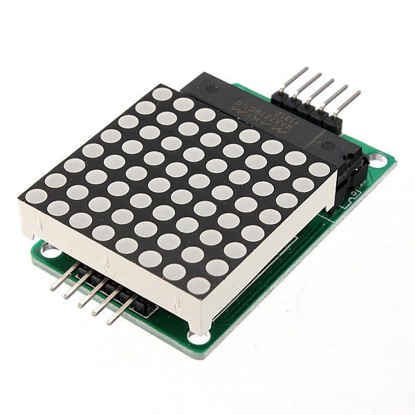
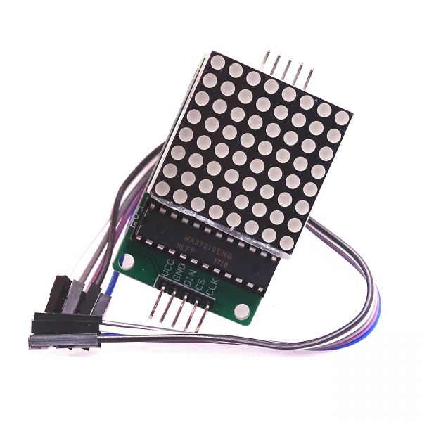
Główne komponenty tego projektu to moduł MAX7219 oraz matryca LED 8x8. MAX7219 to układ scalony, który zarządza wyświetlaniem diod LED, obsługując sygnały komunikacyjne i kontrolne z Arduino. Wykorzystuje interfejs szeregowy, co oznacza, że możemy kontrolować wiele diod LED za pomocą zaledwie kilku pinów z Arduino.
Matryca LED 8x8 składa się z 64 indywidualnych diod LED ułożonych w siatkę. Każdą diodę LED można włączyć lub wyłączyć, wysyłając odpowiednie polecenia przez MAX7219. Umożliwia to wyświetlanie różnych znaków i grafik na matrycy.
Szczegóły karty katalogowej
| Producent | Maxim Integrated |
|---|---|
| Numer części | MAX7219 |
| Napięcie logiczne/IO | 3,3V do 5,5V |
| Napięcie zasilania | 4,0V do 5,5V |
| Prąd wyjściowy (na kanał) | 40 mA max |
| Prąd szczytowy (na kanał) | 100 mA max |
| Wskazówki dotyczące częstotliwości PWM | 100 Hz |
| Progi logiki wejściowej | 2,0V (wysoki) / 0,8V (niski) |
| Spadek napięcia / RDS(on)/ nasycenie | 0,2V typ. |
| Limity termiczne | 150°C |
| Pakiet | 16-DIP |
| Notatki / warianty | Konfiguracja wspólnego anodu |
- Zapewnij odpowiednie zasilanie (4,0V do 5,5V).
- Użyj rezystorów ograniczających prąd dla każdej diody LED, aby zapobiec uszkodzeniu.
- Zachowaj krótkie okablowanie, aby uniknąć zakłóceń.
- Monitoruj odprowadzanie ciepła; użyj radiatora, jeśli to konieczne.
- Podwójnie sprawdź połączenia pinów, aby uniknąć nieporozumień.
Instrukcje dotyczące okablowania
Aby podłączyć MAX7219 do Arduino, podłącz następujące piny:
- Połącz z
VCCpin MAX7219 do 5V Arduino. - Połącz
GNDprzypnij do masy Arduino. - Połącz z
DINpin (Dane Wejściowe) do pinu Arduino 12. - Połącz
CLKprzypnij (Zegar) do pinu Arduino 11. - Połącz z
CSpin (Chip Select) do pinu 10 na Arduino.
Upewnij się, że wszystkie połączenia są pewne przed włączeniem obwodu. Okablowanie jest proste, ale jeśli napotkasz problemy, dokładnie sprawdź połączenia (w wideo o 1:45).
Przykłady kodu i przewodnik
W kodzie zaczynamy od dołączenia biblioteki LedControl, która jest niezbędna do komunikacji z MAX7219. Poniższy fragment inicjalizuje obiekt LedControl:
LedControl lc=LedControl(12,11,10,1);Ta linia ustawia pin danych, pin zegara, pin wyboru układu scalonego oraz liczbę urządzeń (1 w tym przypadku). Następnie, wsetup()funkcja, budzimy MAX7219 i ustawiamy intensywność wyświetlacza:
lc.shutdown(0,false);
lc.setIntensity(0,8);
lc.clearDisplay(0);
To zapewnia, że wyświetlacz jest aktywny i gotowy do wyświetlania znaków. Główną funkcją, która napędza wyświetlacz, jestwriteArduinoOnMatrix(), który kolejno podświetla rzędy matrycy, aby wyświetlić litery.
Demonstracja / Czego się spodziewać
Gdy wszystko jest podłączone, a kod jest przesłany, matryca LED powinna wyświetlać słowo "ROBOJAX". Jeśli wyświetlacz nie działa, sprawdź problemy, takie jak luźne połączenia lub nieprawidłowe przypisania pinów. Dodatkowo upewnij się, że zasilanie jest odpowiednie (w filmie o 2:30).
Rozdziały
- Wprowadzenie (0:00)
- Przegląd sprzętu (0:30)
- Instrukcje dotyczące okablowania (1:45)
- Przegląd kodu (2:15)
- Demonstracja (3:00)
Obrazy
/*
 * This video shows you how to use the MAX7219 module with an 8x8 LED matrix to display text or any characters on the LED.
 * Watch YouTube video: https://youtu.be/AAiDwBKs9uE
 *
 * Written by Ahmad Shamshiri for Robojax.com
 * on February 26, 2017 in Ajax, Ontario, Canada
 * Get this code and other Arduino codes from Robojax.com
 * Learn Arduino step by step in a structured course with all materials, wiring diagrams, and libraries
 * all in one place.

 ****************************
 * Get early access to my videos via Patreon and have your name mentioned at the end of every
 * video I publish on YouTube here: http://robojax.com/L/?id=63 (watch until the end of this video for a list of my Patrons)
 ****************************

 * Or make a donation using PayPal http://robojax.com/L/?id=64

 * This code is "AS IS" without warranty or liability. Free to be used as long as you keep this note intact.
 * This code has been downloaded from Robojax.com
    This program is free software: you can redistribute it and/or modify
    it under the terms of the GNU General Public License as published by
    the Free Software Foundation, either version 3 of the License, or
    (at your option) any later version.

    This program is distributed in the hope that it will be useful,
    but WITHOUT ANY WARRANTY; without even the implied warranty of
    MERCHANTABILITY or FITNESS FOR A PARTICULAR PURPOSE.  See the
    GNU General Public License for more details.

    You should have received a copy of the GNU General Public License
    along with this program.  If not, see <https://www.gnu.org/licenses/>.
*/


// We always have to include the library
// Based on a project posted https://github.com/wayoda/LedControl
#include "LedControl.h"

 /*
  Now we need a LedControl to work with.
  // Customized for RoboJax.com on February 26, 2017 in Ajax, Ontario, Canada.
  ***** These pin numbers will probably not work with your hardware *****
  pin 12 is connected to the DataIn
  pin 11 is connected to the CLK
  pin 10 is connected to CS
  We have only a single MAX72XX.
  */
 LedControl lc=LedControl(12,11,10,1);

 /* we always wait a bit between updates of the display */
 unsigned long delaytime=600;

 void setup() {
   /*
    The MAX72XX is in power-saving mode on startup,
    we have to do a wakeup call
    */
   lc.shutdown(0,false);
   /* Set the brightness to a medium value */
   lc.setIntensity(0,8);
   /* and clear the display */
   lc.clearDisplay(0);
 }

 /*
  This method will display the characters for the
  word "Arduino" one after the other on the matrix.
  (you need at least 5x7 LEDs to see the whole characters)
  */
 void writeArduinoOnMatrix() {
   /* here is the data for the characters */

   // K
   byte R[8]={B11111100,B10000100,B10000100,B11111000,B10100000,B10010000,B10001000,B10000100};
   byte O[8]={B00011000,B00100100,B01000010,B01000010,B01000010,B01000010,B00100100,B00011000};
   byte B[8]={B11111100,B10000100,B10000100,B11111000,B10001000,B10000100,B10000100,B11111100};
   byte J[8]={B00011110,B00000100,B00000100,B00000100,B10000100,B10000100,B01000100,B00111000};
   byte A[8]={B00111000,B01000100,B10000010,B11111110,B10000010,B10000010,B10000010,B10000010};
   byte X[8]={ B10000001,B01000010,B00100100,B00011000,B00011000,B00100100,B01000010,B10000001};
   byte love[8]={ B00000000,B01100110,B10011001,B10011001,B10000001,B01000010,B00100100,B00011000};


   /* Letter R */
   for (int i=0; i<8; i++){
   lc.setRow(0,i,R[i]);

   }

   delay(delaytime);
   for(int i=0; i<8; i++){
       lc.setRow(0,i,0);// this is for blank
   }
 //////////////// END of Letter R ///////

   /* Letter O */
   for (int i=0; i<8; i++){
   lc.setRow(0,i,O[i]);

   }

   delay(delaytime);
   for(int i=0; i<8; i++){
       lc.setRow(0,i,0);// this is for blank
   }
 //////////////// END of Letter O ///////


   /* Letter B */
   for (int i=0; i<8; i++){
   lc.setRow(0,i,B[i]);

   }

   delay(delaytime);
   for(int i=0; i<8; i++){
       lc.setRow(0,i,0);// this is for blank
   }
 //////////////// END of Letter B ///////

   /* Letter O */
   for (int i=0; i<8; i++){
   lc.setRow(0,i,O[i]);

   }

   delay(delaytime);
   for(int i=0; i<8; i++){
       lc.setRow(0,i,0);// this is for blank
   }
 //////////////// END of Letter O ///////

   /* Letter J */
   for (int i=0; i<8; i++){
   lc.setRow(0,i,J[i]);

   }

   delay(delaytime);
   for(int i=0; i<8; i++){
       lc.setRow(0,i,0);// this is for blank
   }
 //////////////// END of Letter J ///////

   /* Letter A */
   for (int i=0; i<8; i++){
   lc.setRow(0,i,A[i]);

   }

   delay(delaytime);
   for(int i=0; i<8; i++){
       lc.setRow(0,i,0);// this is for blank
   }
 //////////////// END of Letter A ///////

   /* Letter X */
   for (int i=0; i<8; i++){
   lc.setRow(0,i,X[i]);

   }

   delay(delaytime);
   for(int i=0; i<8; i++){
       lc.setRow(0,i,0);// this is for blank
   }
 //////////////// END of Letter X ///////


   /* love */
   for (int i=0; i<8; i++){
   lc.setRow(0,i,love[i]);

   }

   delay(delaytime);
   delay(delaytime);
   for(int i=0; i<8; i++){
       lc.setRow(0,i,0);// this is for blank
   }
 //////////////// END of Letter love ///////

 }// writeArduinoOnMatrix()  end


 void loop() {
   writeArduinoOnMatrix();

}/*
* This video shows you how to use the MAX7219 module with an 8x8 LED matrix to display text or any characters on the LED.
* Watch YouTube video: https://youtu.be/AAiDwBKs9uE
*
* Written by Ahmad S. for Robojax.com
* on February 26, 2017 in Ajax, Ontario, Canada
* Permission granted to share this code, given that this
* note is kept with the code.
* Disclaimer: This code is "AS IS" and for educational purposes only.
*/
// We always have to include the library
// Based on a project posted on https://github.com/wayoda/LedControl
#include "LedControl.h"
/*
Now we need a LedControl object to work with.
// Customized for RoboJax.com on February 26, 2017 in Ajax, Ontario, Canada.
***** These pin numbers will probably not work with your hardware *****
pin 1 is connected to the DataIn
pin 4 is connected to the CLK
pin 53 is connected to CS
We have only a single MAX72XX.
*/
LedControl lc=LedControl(1,4,53,1);// this line determines if this code can work with Arduino Mega or Arduino UNO
/* we always wait a bit between updates of the display */
unsigned long delaytime=600;
void setup() {
/*
The MAX72XX is in power-saving mode on startup,
we have to do a wakeup call
*/
lc.shutdown(0,false);
/* Set the brightness to a medium value */
lc.setIntensity(0,8);
/* and clear the display */
lc.clearDisplay(0);
}
/*
This method will display the characters for the
word "Arduino" one after the other on the matrix.
(you need at least 5x7 LEDs to see the whole characters)
*/
void writeArduinoOnMatrix() {
/* here is the data for the characters */
// K
byte R[8]={B11111100,B10000100,B10000100,B11111000,B10100000,B10010000,B10001000,B10000100};
byte O[8]={B00011000,B00100100,B01000010,B01000010,B01000010,B01000010,B00100100,B00011000};
byte B[8]={B11111100,B10000100,B10000100,B11111000,B10001000,B10000100,B10000100,B11111100};
byte J[8]={B00011110,B00000100,B00000100,B00000100,B10000100,B10000100,B01000100,B00111000};
byte A[8]={B00111000,B01000100,B10000010,B11111110,B10000010,B10000010,B10000010,B10000010};
byte X[8]={ B10000001,B01000010,B00100100,B00011000,B00011000,B00100100,B01000010,B10000001};
byte love[8]={ B00000000,B01100110,B10011001,B10011001,B10000001,B01000010,B00100100,B00011000};
/* Letter R */
for (int i=0; i<8; i++){
lc.setRow(0,i,R[i]);
}
delay(delaytime);
for(int i=0; i<8; i++){
lc.setRow(0,i,0);// this is for blank
}
/////////////// END of Letter R ///////
/* Letter O */
for (int i=0; i<8; i++){
lc.setRow(0,i,O[i]);
}
delay(delaytime);
for(int i=0; i<8; i++){
lc.setRow(0,i,0);// this is for blank
}
/////////////// END of Letter O ///////
/* Letter B */
for (int i=0; i<8; i++){
lc.setRow(0,i,B[i]);
}
delay(delaytime);
for(int i=0; i<8; i++){
lc.setRow(0,i,0);// this is for blank
}
/////////////// END of Letter B ///////
/* Letter O */
for (int i=0; i<8; i++){
lc.setRow(0,i,O[i]);
}
delay(delaytime);
for(int i=0; i<8; i++){
lc.setRow(0,i,0);// this is for blank
}
/////////////// END of Letter O ///////
/* Letter J */
for (int i=0; i<8; i++){
lc.setRow(0,i,J[i]);
}
delay(delaytime);
for(int i=0; i<8; i++){
lc.setRow(0,i,0);// this is for blank
}
/////////////// END of Letter J ///////
/* Letter A */
for (int i=0; i<8; i++){
lc.setRow(0,i,A[i]);
}
delay(delaytime);
for(int i=0; i<8; i++){
lc.setRow(0,i,0);// this is for blank
}
/////////////// END of Letter A ///////
/* Letter X */
for (int i=0; i<8; i++){
lc.setRow(0,i,X[i]);
}
delay(delaytime);
for(int i=0; i<8; i++){
lc.setRow(0,i,0);// this is for blank
}
/////////////// END of Letter X ///////
/* love */
for (int i=0; i<8; i++){
lc.setRow(0,i,love[i]);
}
delay(delaytime);
delay(delaytime);
for(int i=0; i<8; i++){
lc.setRow(0,i,0);// this is for blank
}
/////////////// END of love ///////
}// writeArduinoOnMatrix() end
void loop() {
writeArduinoOnMatrix();
}Rzeczy, których możesz potrzebować
-
AmazonMax7219 8x8 Matrix on Amazonamzn.to
-
AllegroMax7219 8x8 Matrix on eBayebay.us
-
AliExpressMax7219 8x8 Matrix on AliExpresss.click.aliexpress.com
Zasoby i odniesienia
-
DokumentacjaView different board pin assignments for SPIarduino.cc
-
Zewnętrzny
-
Wewnętrzny
Pliki📁
Inne pliki
-
Biblioteka matryc MAX7219 od Robojax
robojax-MAX7219-matrix.zip0.01 MB -
8-Digit LED Display Library (from Robojax.com)
robojax_MAX7291_8_digits.zip