8x8 LED-matrix met een MAX7219 Arduino-module
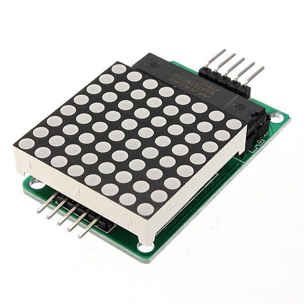
In deze tutorial leren we hoe we een 8x8 LED-matrix kunnen aansturen met een MAX7219-module en een Arduino. De MAX7219 vereenvoudigt de controle over meerdere LED's, waardoor we gemakkelijk tekens en patronen kunnen weergeven. Aan het einde van dit project ben je in staat om het woord "ROBOJAX" op de matrix weer te geven.
Om dit te bereiken, zullen we de LedControl-bibliotheek gebruiken, die speciaal is ontworpen voor interfacing met de MAX7219. Deze bibliotheek stelt ons in staat om gegevens naar de LED-matrix te verzenden met minimale inspanning. Als je een duidelijker begrip wilt van de bedrading en de code, zorg er dan voor dat je de bijbehorende video bekijkt (in video om 0:30).
Hardware Uitleg
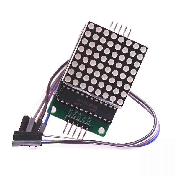
De belangrijkste componenten van dit project zijn de MAX7219-module en de 8x8 LED-matrix. De MAX7219 is een geïntegreerde schakeling die het display van de LEDs beheert, en de communicatie- en controlesignalen van de Arduino afhandelt. Het maakt gebruik van een seriële interface, wat betekent dat we veel LEDs kunnen aansturen met slechts een paar pinnen van de Arduino.
De 8x8 LED-matrix bestaat uit 64 individuele LED's die in een raster zijn gerangschikt. Elke LED kan aan of uit worden gezet door de juiste commando's via de MAX7219 te verzenden. Dit maakt het mogelijk om verschillende tekens en graphics op de matrix weer te geven.
Datasheet Gegevens
| Fabrikant | Maxim Integrated |
|---|---|
| Onderdeelnummer | MAX7219 |
| Logica/IO spanning | 3,3V tot 5,5V |
| Voedingsspanning | 4,0V tot 5,5V |
| Uitgangsstroom (per kanaal) | 40 mA max |
| Piekstroom (per kanaal) | 100 mA max |
| PWM frequentie richtlijnen | 100 Hz |
| Ingangslogische drempels | 2,0V (hoog) / 0,8V (laag) |
| Spanningsval / RDS(on)/ verzadiging | 0,2V typ. |
| Thermische limieten | 150°C |
| Pakket | 16-DIP |
| Notities / varianten | Gemeenschappelijke anodeconfiguratie |
- Zorg voor een juiste voeding (4,0V tot 5,5V).
- Gebruik stroombeperkende weerstanden voor elke LED om schade te voorkomen.
- Houd de bedrading kort om interferentie te voorkomen.
- Monitor de warmteafvoer; gebruik indien nodig een koellichaam.
- Controleer de pinverbindingen dubbel om miscommunicatie te voorkomen.
Bedradinginstructies
Om de MAX7219 aan de Arduino te verbinden, sluit je de volgende pinnen aan:
- Verbind de
VCCpin van de MAX7219 naar de 5V van de Arduino. - Verbind de
GNDpin naar de aarde van de Arduino. - Verbind de
DINpin (Data In) naar Arduino pin 12. - Verbind de
CLKpin (Klok) naar Arduino pin 11. - Verbind de
CSpin (Chip Select) naar Arduino pin 10.
Zorg ervoor dat je controleert of alle verbindingen veilig zijn voordat je de schakeling inschakelt. De bedrading is eenvoudig, maar als je problemen tegenkomt, controleer dan de verbindingen zorgvuldig (in de video om 1:45).
Codevoorbeelden en Stappenplan
In de code beginnen we met het opnemen van de LedControl-bibliotheek, die essentieel is voor de communicatie met de MAX7219. Het volgende fragment initialiseert het LedControl-object:
LedControl lc=LedControl(12,11,10,1);Deze regel stelt de datapin, klokpin, chipselectpin en het aantal apparaten in (1, in dit geval). Vervolgens, in desetup()functie, we wekken de MAX7219 en stellen de helderheid van het display in:
lc.shutdown(0,false);
lc.setIntensity(0,8);
lc.clearDisplay(0);
Dit zorgt ervoor dat het scherm actief is en klaar om tekens weer te geven. De belangrijkste functie die het scherm aanstuurt iswriteArduinoOnMatrix(), die de rijen van de matrix achtereenvolgens verlicht om letters weer te geven.
Demonstratie / Wat te Verwachten
Zodra alles is aangesloten en de code is geüpload, zou de LED-matrix het woord "ROBOJAX" moeten weergeven. Als de weergave niet werkt, controleer dan op problemen zoals losse verbindingen of onjuiste pin-toewijzingen. Zorg er bovendien voor dat de voeding voldoende is (in de video om 2:30).
Hoofdstukken
- Inleiding (0:00)
- Hardware Overzicht (0:30)
- Bedradinginstructies (1:45)
- Code Walkthrough (2:15)
- Demonstratie (3:00)
Afbeeldingen
/*
 * This video shows you how to use the MAX7219 module with an 8x8 LED matrix to display text or any characters on the LED.
 * Watch YouTube video: https://youtu.be/AAiDwBKs9uE
 *
 * Written by Ahmad Shamshiri for Robojax.com
 * on February 26, 2017 in Ajax, Ontario, Canada
 * Get this code and other Arduino codes from Robojax.com
 * Learn Arduino step by step in a structured course with all materials, wiring diagrams, and libraries
 * all in one place.

 ****************************
 * Get early access to my videos via Patreon and have your name mentioned at the end of every
 * video I publish on YouTube here: http://robojax.com/L/?id=63 (watch until the end of this video for a list of my Patrons)
 ****************************

 * Or make a donation using PayPal http://robojax.com/L/?id=64

 * This code is "AS IS" without warranty or liability. Free to be used as long as you keep this note intact.
 * This code has been downloaded from Robojax.com
    This program is free software: you can redistribute it and/or modify
    it under the terms of the GNU General Public License as published by
    the Free Software Foundation, either version 3 of the License, or
    (at your option) any later version.

    This program is distributed in the hope that it will be useful,
    but WITHOUT ANY WARRANTY; without even the implied warranty of
    MERCHANTABILITY or FITNESS FOR A PARTICULAR PURPOSE.  See the
    GNU General Public License for more details.

    You should have received a copy of the GNU General Public License
    along with this program.  If not, see <https://www.gnu.org/licenses/>.
*/


// We always have to include the library
// Based on a project posted https://github.com/wayoda/LedControl
#include "LedControl.h"

 /*
  Now we need a LedControl to work with.
  // Customized for RoboJax.com on February 26, 2017 in Ajax, Ontario, Canada.
  ***** These pin numbers will probably not work with your hardware *****
  pin 12 is connected to the DataIn
  pin 11 is connected to the CLK
  pin 10 is connected to CS
  We have only a single MAX72XX.
  */
 LedControl lc=LedControl(12,11,10,1);

 /* we always wait a bit between updates of the display */
 unsigned long delaytime=600;

 void setup() {
   /*
    The MAX72XX is in power-saving mode on startup,
    we have to do a wakeup call
    */
   lc.shutdown(0,false);
   /* Set the brightness to a medium value */
   lc.setIntensity(0,8);
   /* and clear the display */
   lc.clearDisplay(0);
 }

 /*
  This method will display the characters for the
  word "Arduino" one after the other on the matrix.
  (you need at least 5x7 LEDs to see the whole characters)
  */
 void writeArduinoOnMatrix() {
   /* here is the data for the characters */

   // K
   byte R[8]={B11111100,B10000100,B10000100,B11111000,B10100000,B10010000,B10001000,B10000100};
   byte O[8]={B00011000,B00100100,B01000010,B01000010,B01000010,B01000010,B00100100,B00011000};
   byte B[8]={B11111100,B10000100,B10000100,B11111000,B10001000,B10000100,B10000100,B11111100};
   byte J[8]={B00011110,B00000100,B00000100,B00000100,B10000100,B10000100,B01000100,B00111000};
   byte A[8]={B00111000,B01000100,B10000010,B11111110,B10000010,B10000010,B10000010,B10000010};
   byte X[8]={ B10000001,B01000010,B00100100,B00011000,B00011000,B00100100,B01000010,B10000001};
   byte love[8]={ B00000000,B01100110,B10011001,B10011001,B10000001,B01000010,B00100100,B00011000};


   /* Letter R */
   for (int i=0; i<8; i++){
   lc.setRow(0,i,R[i]);

   }

   delay(delaytime);
   for(int i=0; i<8; i++){
       lc.setRow(0,i,0);// this is for blank
   }
 //////////////// END of Letter R ///////

   /* Letter O */
   for (int i=0; i<8; i++){
   lc.setRow(0,i,O[i]);

   }

   delay(delaytime);
   for(int i=0; i<8; i++){
       lc.setRow(0,i,0);// this is for blank
   }
 //////////////// END of Letter O ///////


   /* Letter B */
   for (int i=0; i<8; i++){
   lc.setRow(0,i,B[i]);

   }

   delay(delaytime);
   for(int i=0; i<8; i++){
       lc.setRow(0,i,0);// this is for blank
   }
 //////////////// END of Letter B ///////

   /* Letter O */
   for (int i=0; i<8; i++){
   lc.setRow(0,i,O[i]);

   }

   delay(delaytime);
   for(int i=0; i<8; i++){
       lc.setRow(0,i,0);// this is for blank
   }
 //////////////// END of Letter O ///////

   /* Letter J */
   for (int i=0; i<8; i++){
   lc.setRow(0,i,J[i]);

   }

   delay(delaytime);
   for(int i=0; i<8; i++){
       lc.setRow(0,i,0);// this is for blank
   }
 //////////////// END of Letter J ///////

   /* Letter A */
   for (int i=0; i<8; i++){
   lc.setRow(0,i,A[i]);

   }

   delay(delaytime);
   for(int i=0; i<8; i++){
       lc.setRow(0,i,0);// this is for blank
   }
 //////////////// END of Letter A ///////

   /* Letter X */
   for (int i=0; i<8; i++){
   lc.setRow(0,i,X[i]);

   }

   delay(delaytime);
   for(int i=0; i<8; i++){
       lc.setRow(0,i,0);// this is for blank
   }
 //////////////// END of Letter X ///////


   /* love */
   for (int i=0; i<8; i++){
   lc.setRow(0,i,love[i]);

   }

   delay(delaytime);
   delay(delaytime);
   for(int i=0; i<8; i++){
       lc.setRow(0,i,0);// this is for blank
   }
 //////////////// END of Letter love ///////

 }// writeArduinoOnMatrix()  end


 void loop() {
   writeArduinoOnMatrix();

}/*
* This video shows you how to use the MAX7219 module with an 8x8 LED matrix to display text or any characters on the LED.
* Watch YouTube video: https://youtu.be/AAiDwBKs9uE
*
* Written by Ahmad S. for Robojax.com
* on February 26, 2017 in Ajax, Ontario, Canada
* Permission granted to share this code, given that this
* note is kept with the code.
* Disclaimer: This code is "AS IS" and for educational purposes only.
*/
// We always have to include the library
// Based on a project posted on https://github.com/wayoda/LedControl
#include "LedControl.h"
/*
Now we need a LedControl object to work with.
// Customized for RoboJax.com on February 26, 2017 in Ajax, Ontario, Canada.
***** These pin numbers will probably not work with your hardware *****
pin 1 is connected to the DataIn
pin 4 is connected to the CLK
pin 53 is connected to CS
We have only a single MAX72XX.
*/
LedControl lc=LedControl(1,4,53,1);// this line determines if this code can work with Arduino Mega or Arduino UNO
/* we always wait a bit between updates of the display */
unsigned long delaytime=600;
void setup() {
/*
The MAX72XX is in power-saving mode on startup,
we have to do a wakeup call
*/
lc.shutdown(0,false);
/* Set the brightness to a medium value */
lc.setIntensity(0,8);
/* and clear the display */
lc.clearDisplay(0);
}
/*
This method will display the characters for the
word "Arduino" one after the other on the matrix.
(you need at least 5x7 LEDs to see the whole characters)
*/
void writeArduinoOnMatrix() {
/* here is the data for the characters */
// K
byte R[8]={B11111100,B10000100,B10000100,B11111000,B10100000,B10010000,B10001000,B10000100};
byte O[8]={B00011000,B00100100,B01000010,B01000010,B01000010,B01000010,B00100100,B00011000};
byte B[8]={B11111100,B10000100,B10000100,B11111000,B10001000,B10000100,B10000100,B11111100};
byte J[8]={B00011110,B00000100,B00000100,B00000100,B10000100,B10000100,B01000100,B00111000};
byte A[8]={B00111000,B01000100,B10000010,B11111110,B10000010,B10000010,B10000010,B10000010};
byte X[8]={ B10000001,B01000010,B00100100,B00011000,B00011000,B00100100,B01000010,B10000001};
byte love[8]={ B00000000,B01100110,B10011001,B10011001,B10000001,B01000010,B00100100,B00011000};
/* Letter R */
for (int i=0; i<8; i++){
lc.setRow(0,i,R[i]);
}
delay(delaytime);
for(int i=0; i<8; i++){
lc.setRow(0,i,0);// this is for blank
}
/////////////// END of Letter R ///////
/* Letter O */
for (int i=0; i<8; i++){
lc.setRow(0,i,O[i]);
}
delay(delaytime);
for(int i=0; i<8; i++){
lc.setRow(0,i,0);// this is for blank
}
/////////////// END of Letter O ///////
/* Letter B */
for (int i=0; i<8; i++){
lc.setRow(0,i,B[i]);
}
delay(delaytime);
for(int i=0; i<8; i++){
lc.setRow(0,i,0);// this is for blank
}
/////////////// END of Letter B ///////
/* Letter O */
for (int i=0; i<8; i++){
lc.setRow(0,i,O[i]);
}
delay(delaytime);
for(int i=0; i<8; i++){
lc.setRow(0,i,0);// this is for blank
}
/////////////// END of Letter O ///////
/* Letter J */
for (int i=0; i<8; i++){
lc.setRow(0,i,J[i]);
}
delay(delaytime);
for(int i=0; i<8; i++){
lc.setRow(0,i,0);// this is for blank
}
/////////////// END of Letter J ///////
/* Letter A */
for (int i=0; i<8; i++){
lc.setRow(0,i,A[i]);
}
delay(delaytime);
for(int i=0; i<8; i++){
lc.setRow(0,i,0);// this is for blank
}
/////////////// END of Letter A ///////
/* Letter X */
for (int i=0; i<8; i++){
lc.setRow(0,i,X[i]);
}
delay(delaytime);
for(int i=0; i<8; i++){
lc.setRow(0,i,0);// this is for blank
}
/////////////// END of Letter X ///////
/* love */
for (int i=0; i<8; i++){
lc.setRow(0,i,love[i]);
}
delay(delaytime);
delay(delaytime);
for(int i=0; i<8; i++){
lc.setRow(0,i,0);// this is for blank
}
/////////////// END of love ///////
}// writeArduinoOnMatrix() end
void loop() {
writeArduinoOnMatrix();
}Dingen die je misschien nodig hebt
-
AmazonMax7219 8x8 Matrix on Amazonamzn.to
-
eBayMax7219 8x8 Matrix on eBayebay.us
-
AliExpressMax7219 8x8 Matrix on AliExpresss.click.aliexpress.com
Hulpmiddelen en referenties
-
DocumentatieView different board pin assignments for SPIarduino.cc
-
Extern
Bestanden📁
Andere bestanden
-
MAX7219 Matrix Bibliotheek van Robojax
robojax-MAX7219-matrix.zip0.01 MB -
8-Digit LED Display Library (from Robojax.com)
robojax_MAX7291_8_digits.zip